
The Paths tool is not exactly a selection tool, but it does offer a powerful way to build complicated selections. You can access it from the Toolbox (see Figure 13-54), from Image: Tools > Paths, or by pressing ![]() . The keyboard shortcut comes from Bézier curves, which is another name for paths.
. The keyboard shortcut comes from Bézier curves, which is another name for paths.
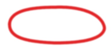
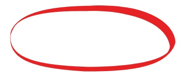
A Bézier curve is a powerful mathematical tool for describing sophisticated curves. Although the mathematics are complicated, the curves, or paths, are fairly easy to create using a small set of anchor points and the corresponding handles of these points. Modifying the curve by moving, adding, or removing anchor points or by changing the orientation and length of the handles is easy. Figure 13-55 shows four different paths. As you can see, paths can be closed or open and may contain straight or curved segments, or both. When constructing a path, you can undo any action, which is not possible with most selection tools, including the Scissors Select tool and the Foreground Select tool. Every path you build is saved in the current image and can be retrieved in the Paths dialog, which is initially a part of the multi-dialog window. If it’s no longer open, you can open the dialog from the Image: Windows > Dockable Dialogs menu. The Paths tab appears after the Layers and Channels tabs. When visible, the Paths dialog shows the paths that exist in the current image. By default, the paths are invisible, but clicking the left side of the line reveals the eye icon, which indicates that the path is now visible.

After creating a path, you can convert it to a selection or stroke it, which allows you to draw on the image. You can even convert the selection to the SVG format for vector graphics (see Chapter 20).
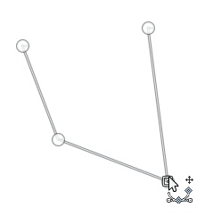
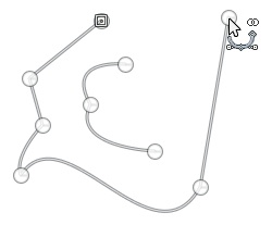
When you select the Paths tool, the mouse pointer is accompanied by the complicated icon shown in Figure 13-56. The tiny + sign means that clicking will add anchor points to the path. The points you have already placed appear as filled circles, except the most recent one, which appears as an empty circle. Straight lines link the points.
If you move the pointer close to an existing anchor point or a segment, the + sign changes to the move sign (crossed arrows). In Figure 13-57, we clicked and dragged an existing anchor point, which then became the current point.
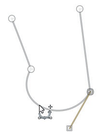

If you click and drag on a segment, the resulting effect depends on the status of the POLYGONAL checkbox in the tool options. If it is unchecked, the segment is deformed as shown in Figure 13-58. Handles extend from both ends of the resulting arc. If you move the handle, the arc is deformed, as shown in Figure 13-59.
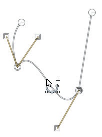
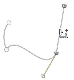
If you click and drag a segment when the POLYGONAL box is checked, the segment is moved but not deformed. To make this possible without separating the segments, the adjacent segments must be deformed instead. In Figure 13-60, we moved the curved segment down, and both straight segments were lengthened. In Figure 13-61, we moved the straight segment on the right farther to the right, and the curved segment was deformed.
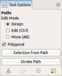
The Paths tool options are shown in Figure 13-62. We already discussed the POLYGONAL checkbox. The EDIT MODE option allows you to select among three choices. By default, the DESIGN button is checked; in this mode clicking outside the path adds a new point. When you add a new point, a segment is placed between the new point and the previous one. If you switch to another tool and then back to the Paths tool, you can either continue the existing path or build a disjointed path, a single path that looks like two separate paths (Figure 13-63). To continue an existing path, click an existing anchor point and then add your new point. To build a disjointed path, click the existing path twice, activate Design mode, and begin adding points without first clicking an existing point.

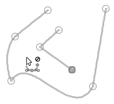
If you click the EDIT radio button (or press the ![]() key), you can change the tool’s behavior. When outside of the anchor points or segments, the mouse pointer is not operational, as shown by the circle with a line through it in Figure 13-64.
key), you can change the tool’s behavior. When outside of the anchor points or segments, the mouse pointer is not operational, as shown by the circle with a line through it in Figure 13-64.
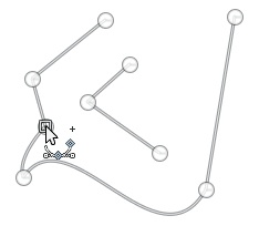
If the pointer is close to a segment, the mouse pointer is accompanied by a tiny + sign, which means that you can add a new anchor point at this location, as shown in Figure 13-65.
If the pointer is close to an anchor point, the mouse pointer normally changes to the Move icon, which means you can move that point. But the effect of moving a point depends on the status of the POLYGONAL option. When this option is checked, the anchor moves; otherwise, a handle is moved, and the curve is deformed.
Depending on the direction of the move, a different handle appears; each handle corresponds to one of the curves attached to the anchor point. In Figure 13-66, both handles are visible.
Finally, if the current point (the one denoted with a hollow circle) is at the end of an open path and the mouse pointer is close to a different end point, the pointer changes to a link icon, as shown in Figure 13-67, and clicking draws a segment between the two endpoints. This closes the path.

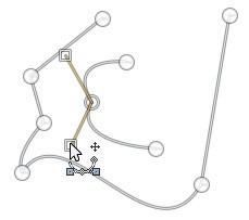
If you click the MOVE radio button in the tool options (or press the ![]() key), the mouse pointer is always accompanied by the move sign. If you click a segment or anchor point of a path component, you can move it, as shown in Figure 13-68. If you click and drag outside of the path, you move the whole active path.
key), the mouse pointer is always accompanied by the move sign. If you click a segment or anchor point of a path component, you can move it, as shown in Figure 13-68. If you click and drag outside of the path, you move the whole active path.
You can also move a completed path without altering it with the Move tool. To do this, select the Move tool and click the rightmost button in its options dialog. You can also use the transformation tools on a path to apply perspective or rotation, for example.
Most often, a completed path is either converted to a selection or used to paint on the image. The path can be converted to a selection by clicking the SELECTION FROM PATH button in the options dialog.
Figure 13-69 shows the result when we do this for the path in Figure 13-68. The unselected parts appear pink because we’ve turned on Quick Mask (![]() ).
).
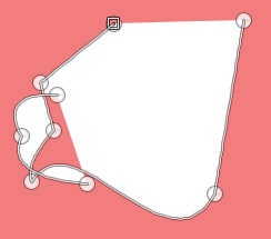
As expected, marching ants follow the path, and the outline of the selection is sharp.
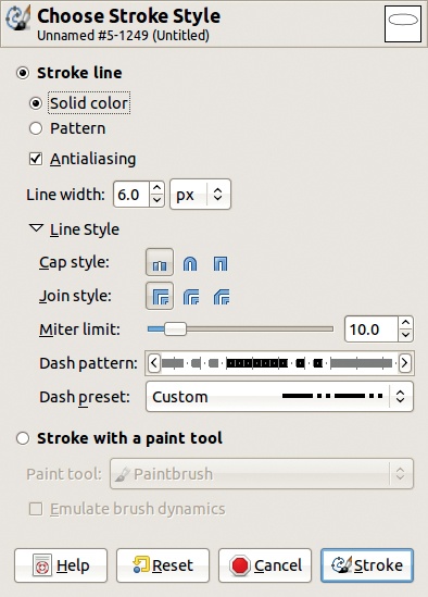
Stroking the path is equivalent to painting on the image along the path. Clicking the STROKE PATH button opens the dialog shown in Figure 13-70. This dialog is where you specify the characteristics of the stroke that will be painted along the path. First, you must choose whether to stroke the line or to stroke with a paint tool.

If you choose to stroke the line, you can specify the width of the line, whether to use a SOLID COLOR (the foreground color) or a PATTERN, and which LINE STYLE to use. The LINE STYLE choices include the following:
CAP STYLE affects the ends of the segments.
JOIN STYLE affects the angle between two segments.
MITER LIMIT also alters the appearance of joints. A level of zero results in a joint that ends abruptly where the two segments intersect, whereas a higher level results in a joint that tapers into a point.
The DASH PATTERN is chosen from the DASH PRESET menu (shown in Figure 13-71), which contains a number of preset patterns, as well as an option for creating a custom dash pattern. Adjust the custom pattern by clicking and dragging the line that appears just above the Dash preset menu. The arrow buttons on the ends move the pattern back and forth along the line, changing where it begins and ends. Note that the third CAP STYLE can mask the intervals between dashes if they are too short. This effect will not be visible in the preview, but it will be apparent once you finalize the changes (see Figure 13-72). The path is still visible beneath the strokes, but it is not itself a part of the image. If you printed this image, for example, the handles on the left would not appear.
The ANTIALIASING option is best left checked, as usual.

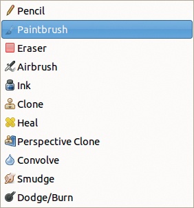
If you select the STROKE WITH A PAINT TOOL option, you can choose from the paint tools shown in Figure 13-73. Figure 13-74 shows the result of stroking with the Paintbrush tool with a Hardness 075 brush scaled to size 20. For Figure 13-75, we used the Ink tool and checked the EMULATE BRUSH DYNAMICS checkbox. See Chapter 15, and particularly Paint Dynamics, for more details about paint dynamics.
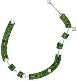
You can also stroke the path with a pattern by choosing STROKE LINE and then PATTERN. You must choose the pattern after opening the Choose Stroke Style dialog by selecting the pattern in the Patterns dialog, initially in the multi-dialog window. The path in Figure 13-76 was stroked using the Pine pattern.
A path differs from a selection in the following ways:
Although only one selection is available at a time, a given image can contain several paths. If you save the image in the XCF format, for example, the paths are saved with it and are available the next time you open it. Note that this is also true if you export the image in the TIFF format.
When you are building a path, you can undo any action.
Existing paths are available in the Paths dialog, which is a dockable dialog, normally open in the multi-dialog window.
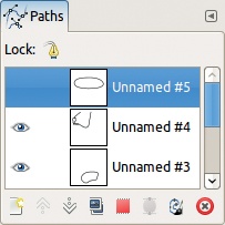
Figure 13-77 shows a Paths dialog containing three paths. The top one, whose row is emphasized, is the current path. The other two are visible in the Image window, as the eye icon is visible. When a path is visible in the Image window, make it the current path by selecting the Paths tool and clicking it. Clicking its row in the Paths dialog has the same result. If the Lock is active, it prevents any change to the current path.
As in the Layers or Channels dialogs, each row in the Paths dialog has a position for a link. This is explained in more detail in Chapter 11. A path can be linked to one or more layers and channels and can then be deformed using any of the transformation tools—in the same way as the other linked components.
Right-clicking in the Paths dialog brings up the Paths menu, shown in Figure 13-78. This menu can also be accessed via the configure button at the top right of the dialog. The eight most useful entries in this menu also have corresponding buttons located at the bottom of the dialog.
EDIT PATH ATTRIBUTES only allows you to change the path name, which can also be done by double-clicking in the corresponding row.
NEW PATH creates a new empty path. Another way to create a new path is to click in the image with the Paths tool selected, without first clicking a visible path.
RAISE PATH and LOWER PATH move the paths up or down in the dialog, but this has no effect on the function of the paths, and you can also rearrange them by clicking and dragging their rows in the dialog.
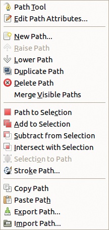
DUPLICATE PATH and DELETE PATH have obvious meanings. Clicking and dragging a row to the delete icon also deletes that path.
MERGE VISIBLE PATHS is a way to build one path from several, but all the paths being merged must be visible. Make them visible (by clicking the eye icon) before using this menu entry.
The next four menu entries are equivalent to the SELECTION FROM PATH button in the options dialog. The difference is that in the options dialog, you must make additional selections to control how the new selection is combined with the existing one, whereas in the Paths menu, four distinct entries correspond to the different combination methods. Note that the default method (replacing the existing selection) can also be accomplished by applying Image: Select > From Path or by pressing ![]() .
.
SELECTION TO PATH uses the marching ants of the existing selection to build a new path. Or you can apply Image: Select > To Path to do this.
STROKE PATH does the same thing as the corresponding button in the options dialog.
COPY PATH and PASTE PATH allow you to copy a path from one image to another. You can also do this by clicking and dragging a path from the Paths dialog to the Image window.
EXPORT PATH converts the path to the SVG format. In the dialog that opens, you can choose whether to export only the current path or all the paths in the image.
IMPORT PATH converts an existing SVG file into a path. This can be handy for creating extremely complicated paths, which would be beyond the capabilities of the Paths tool. Note that GIMP can also load an SVG file as an image.
Paths can also be used in conjunction with the Text tool. Text can be converted to a path, or it can be typed along a path. Refer to 15.8 The Text Tool for more details.