
Although GIMP wasn’t designed for web development or design, it does include some useful tools for preparing images for the Web, including two found in the Image: Filter > Web menu, which let you delimit areas in an image so you can make something happen when a visitor clicks or hovers over those areas. This menu also contains a tool for handling GIF images.
Image: Filters > Web > Image Map uses an image to build a clickable map that you can integrate into a web page. The map is divided into non-overlapping regions, and a link is attached to each region. When users click in one of the regions, they are taken to the corresponding link.
The Image Map dialog, shown in Figure 8-14, has two main regions: the source of the image map displayed on the left, and the URLs attached to regions of the image displayed on the right. The dialog also has a row of buttons at the top for editing the defined area and columns of buttons along both sides of the image preview. The left column contains buttons for selecting and defining areas and editing information linked to an area. The right column contains buttons for moving, editing, or deleting information linked to an area. To create the image map, click one of the three blue buttons defining a geometric shape, draw the shape on the image, and then attach a URL to it.
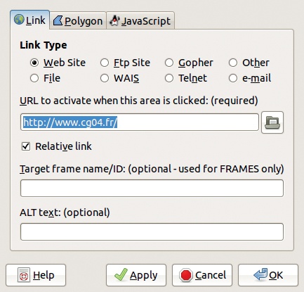
To draw a rectangle or a circle, click and drag to create the shape and then click once more to complete the shape. To draw a polygon, click at each vertex and double-click to place the final point and complete the shape. Once the shape is complete, a dialog similar to the one shown in Figure 8-15 appears. Choose the link type and then enter or paste in the link address. You can either use an absolute address beginning with http:// or a relative address that is an internal link within your website. You can also enter ALT TEXT to display when the mouse hovers over the link and in the event the link doesn’t work.
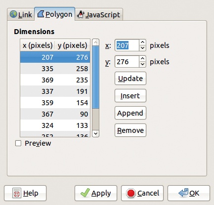
The second tab of the Area Settings dialog varies depending on the shape of the map. Here you can change some of the coordinates manually. Figure 8-16 shows the dialog for a polygon. The third tab, not shown, can be used to define JavaScript sequences and link them to specific events.

One TOOLS menu is accessed by clicking the triangle button at the top left of the another is accessed by right-clicking in the Image Map dialog while the pointer is active (Figure 8-17). Although these menus have the same name, they contain different entries. The first Tools menu is for handling the grid and the guides, whereas the second Tools menu contains the four tools also found in the left column of the Image Map dialog and in the MAPPING menu in the menu bar.
The Arrow tool, which appears as an arrow on the left side of the dialog, allows you to select an area that you’ve already defined and move or resize it. The Edit tool allows you to change the parameters associated with the selected area. You can also select the link from the list on the right side of the dialog to select the corresponding area.
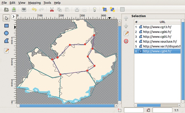
Figure 8-18 shows a map of Provence-Alpes-Côte-d’Azur, with six areas corresponding to French départements outlined and associated with appropriate URLs. If you click one of the shapes while the pointer tool is active, that shape is selected, and you can change the vertices. You can edit the information associated with a shape by double-clicking the URL in the right column or by clicking the Edit button in either of the two columns.
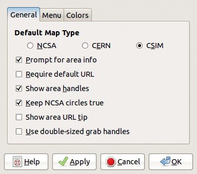
Selecting Edit > Preferences opens the dialog shown in Figure 8-19, which has three tabs. Here, you can set various parameters that adjust the filter interface or the HTML page you are building. On the Menu tab, you can change the number of undo levels or the colors used in the tool dialog, for example.
The grid can be toggled on and off via Tools > Grid, and selecting Tools > Grid Settings opens the dialog shown in Figure 8-20, where you can set the grid’s characteristics. The Image Map grid is similar to the grid used in the Image window, discussed in Chapter 10.
Selecting Tools > Create Guides opens the dialog shown in Figure 8-21. The guides delimit a predefined number of rectangles to which links can be associated. The guides help you to draw a simple map quickly. Note the default number of rectangles is zero, and if you don’t change this number the tools will have no effect.
Selecting Tools > Use GIMP Guides produces a result similar to that produced by the Slice filter, discussed shortly.
When you save the image map (by selecting File > Save, pressing ![]() , or clicking the SAVE button), the filter generates a file with a
, or clicking the SAVE button), the filter generates a file with a .map suffix. This HTML file contains the <img> tag for loading the image and the corresponding <map> tag with definitions of all the <area> tags. Note that the generated file does not necessarily contain the name of the image file to which it refers.


Image: Filters > Web > Semi-Flatten has no dialog. It simulates antialiasing in a GIF image displayed on a web page.
Antialiasing smooths the edges of an object by making pixels along the boundary semitransparent, as shown in Figure 8-22. Because GIF encoding can only represent 0% transparency or 100% transparency, you can’t use anti-aliasing. You could use PNG instead of GIF, but some browsers don’t handle PNG encoding properly. As a way to simulate semitransparency, the Semi-Flatten filter creates pixels that contain a blend of the foreground color and the background color along the edge of the image. To use Semi-Flatten, set the background color to that of the web page background. Figure 8-23 shows the result when the background color is a deep pink.


Image: Filters > Web > Slice is another tool that lets you split an image into sections. Suppose you want to display a large rectangular image on a web page. The image will be cut into smaller rectangular fragments along a grid. Slice lets you choose to display only some of these fragments or to change their appearance when the mouse pointer hovers over them. Slice also lets you set fragments to trigger some specific action when clicked.
For example, say we want to use the image shown in Figure 8-24 as a background for an HTML table. We define areas that correspond to the squares in the table, using a grid that covers the entire image.
Drag new guides from the image sides to the places where you want to make a slice. The result is shown in Figure 8-25.
Click Image: Filters > Web > Slice to finish the job. The image is sliced into several pieces, and a file with the .html suffix is created that contains the code for the HTML table. You can add the contents of this file to the code of your web page. You’ll also need to include the image fragments wherever you keep the web page’s image files.

The options dialog that appears, shown in Figure 8-26, lets you choose the various parameters of the generated files and of the images built from the slices in the initial image. You can name the HTML file, choose where to store it, and enter a prefix and format for the separate cell files, as well as the location where they will be stored. If there are spaces between the images, the web page background will show through. A JavaScript snippet may be called when the mouse is on a cell, but you can choose to freeze the border cells so they can’t be selected or changed.