
The rest of this chapter focuses on multi-image animations. As explained in Method Three: Moving Along a Path, multi-image animations are usually stored in a specific folder with each frame as a separate file named systematically (name-0001.xcf, for example). The number of digits determines the maximum number of frames, which would be 9999 in this example. The number changes, but the name is the same for all frames. The file could be any type handled by GIMP, but XCF is the best choice because it is the only one that handles layers and selections.
In this section, we explore GAP’s primary tool, accessed via Image: Video > Move Path.
This tool copies layers from a source image to a target animation. During the copy process, the layers can be transformed in various ways. The source image can be a single- or multilayer image or a multiframe animation. The target animation must be multiframe because the Move Path tool does not generate frames.
Before using the Move Path tool, open the first frame of the target animation and the source image or animation in GIMP. The source and target images must be of the same type: RGB, indexed, or grayscale, but they cannot be the same file. If you want to duplicate something in an animation using this tool, you must copy the animation first, so the source and target are different files.
To demonstrate the Move Path tool, we chose a multilayer animation as the source and the multiframe animation in Figure 6-43 as the target. The tool’s large and complex dialog is shown in Figure 18-23. To make things clearer, we’ll highlight certain parts of the dialog in subsequent figures.

Because the tool’s purpose is to copy layers to frames, you need to decide which layers to copy to which frames. One copy of the selected layer from the source image is added to each frame of the target.
You choose the source layer in the top-left part of the dialog (Figure 18-23). The menu SOURCE IMAGE/LAYER shows all the layers of the source image or all the frames of the source animation. If the source is a multiframe animation and the individual frames have more than one layer, the layers are flattened before being copied. We chose 1 layer from a 41-layer image as the source.
The STEPMODE menu lets you choose how to select a layer when the source image is multilayer or a frame when it is multiframe. When the source image is a single layer, choose NONE. When the source is a multilayer image, as in our example, you can choose from five different step modes:
LOOP selects the layers in sequence, one for each successive target frame (depending on SPEEDFACTOR, discussed in a bit). When the last layer is the source, the loop starts with this layer, followed by the first layer and then the rest of the layers in order.
LOOP REVERSE is the same as LOOP, except the source layers are selected in reverse order.
ONCE is the same as LOOP, except that copying stops after the last layer instead of looping back to the first layer.
ONCE REVERSE is the same as ONCE, except that source layers are selected in reverse order.
PING PONG selects the layers in sequence first and, once the last layer has been selected, reverses the sequence.
When the source animation is multiframe, STEPMODE offers six equivalent modes whose names all begin with FRAME. When a frame has several layers, the layer selected in one frame is irrelevant because all visible layers in the frame are flattened and the step mode selects among the frames, not the layers.
The last parameter dealing with layer selection is SPEEDFACTOR, which changes how fast the source layers are stepped through. When its value is 1.0, the source and target step are synchronized. When its value is 0.5, the source steps to half speed, so each layer is copied into two successive frames before stepping to the next one. When its value is 2.0, the source steps to double speed, so every other layer is copied.
The speed factor is irrelevant if STEPMODE is NONE or FRAME NONE.
You choose the target animation in the bottom-right part of the dialog (Figure 18-23). The FROM FRAME and TO FRAME cursors delimit the range of target frames. They are set to the full range of the target by default, so the changes are applied to the entire animation, but you can choose to target only a part of the animation.
FORCE VISIBILITY makes all source layers visible even if they are not visible in the source. CLIP TO FRAME clips the copied layers to the image boundaries of the target frames. LAYERSTACK specifies where the copied layers should be inserted in the layer stack of target frames. The default value, 0, is the top of the stack because existing layers are numbered from top to bottom, starting at 0.
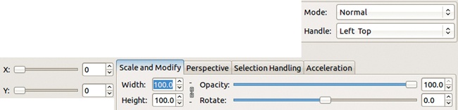
Figure 18-24 shows the sections of the Move Path dialog where you can choose to apply transformations. You can decide where the transformation will be applied using the X and Y coordinates. The HANDLE menu specifies where in the selected layer the origin of these coordinates is located. The possibilities are LEFT TOP, LEFT BOTTOM, RIGHT TOP, RIGHT BOTTOM, and CENTER. CENTER is generally the best choice, especially if rotation or scaling is applied to the layer.
A blending mode can be applied to the layer in the target frame using the MODE menu.
You can scale the source later by setting WIDTH and HEIGHT. These values are percentages. If the chain to the right of the counters is broken, the values can be changed independently.
OPACITY is specified as a percentage. ROTATE is specified in degrees, and a negative value results in a counterclockwise rotation. The rotation center is the image’s handle.
Two more tabs deal with layer transformation. Figure 18-25 shows the PERSPECTIVE tab for transforming perspective. The eight counters specify the factors for the x- and y-coordinates of the four corners of the layer. If the values for all factors are 1.0, no transformation occurs. Scaling with factor 0 moves the point toward the middle. Scaling with factor 2.0 moves the point outward by half the layer’s original dimension. Figure 18-26 shows the layer’s four corners numbered in red. The black numbers show factors, and the dotted outlines show the resulting positions of pixels.


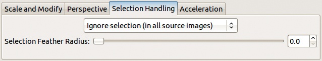
If the source image has a selection, you can control how it’s handled on the SELECTION HANDLING tab shown in Figure 18-27. The menu at the top of the tab has three options:
IGNORE SELECTION (IN ALL SOURCE IMAGES) ignores the selection.
USE SELECTION (FROM INITIAL SOURCE IMAGE) applies the selection found in the first frame to all copied layers. The unselected pixels are transparent.
USE SELECTIONS (FROM ALL SOURCE IMAGES) is the same as the previous choice if the source image is a multilayer animation. If the source is multiframe, then the selection within each frame is used, and if a frame has no selection, that frame is copied in its entirety.
When selection handling is used, you can adjust feathering with the SELECTION FEATHER RADIUS cursor, which changes the number of pixels that are applied in the feathering boundary.
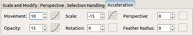
All the preceding parameters (movement, scale, perspective, opacity, rotation, and feathering) are controlled on the ACCELERATION tab (Figure 18-28). Each of those six parameters is associated with a numeric field [–100 to 100] and a small square. If the field value is zero, the movement has a constant speed (i.e., there is no acceleration). If the field value is positive, the movement accelerates, and the small square displays a curve showing the steepness of the acceleration. If the field value is negative, the movement decelerates. You can change the field by typing a value, clicking the small up and down arrows, or dragging in the small square.
A control point is the set of transformation parameters that are applied to a layer. You can define a single control point for all frames being handled by the Move Path tool, or you can define a sequence of control points, which together constitute a control path.
When you have a single control point, the transformation parameters are applied with the same values to all layer copies to the target frames. If you have several control points, they are distributed among target frames. The first and last control points always correspond to the first and last frames. Other control points are usually distributed evenly among rest of the target frames.
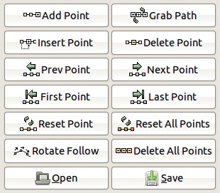
Figure 18-29 shows the section of the dialog that is focused on control points. The number of the current control point is displayed at the top of the dialog, just above the X and Y cursors. Any changes to transformation parameters apply only to the current control point. Note that in the following discussion, when we refer to transformation parameters, we are not referring to the x- and y-coordinates. This dialog has 14 buttons associated with control points.
ADD POINT adds a control point after the last one, with the same transformation parameters as that last point.
GRAB PATH deletes all control points and replaces them with the path’s anchor points (see 13.3 The Paths Tool) in the image from which the Move Path tool was opened. All of these points are initialized with transformation values identical to the current settings.
If you press
 and click GRAB PATH, control points are created for all target frames, with intermediate points defined by the Bézier curve that follows the anchor points.
INSERT POINT duplicates the current control point, and the new copy becomes the current point.
DELETE POINT removes the current control point. Note that undo is not available.
PREV POINT makes the previous control point the current one. When you define key frames (discussed in Key Frames) and press
, the control point from the previous key frame becomes the current control point.NEXT POINT does the same for the next control point or key frame.
FIRST POINT does the same for the first control point (or key frame when pressing
).LAST POINT does the same for the last control point or key frame.
RESET POINT resets the transformation parameters of the current control point to the default values of 100.0 for width, height, and opacity; 0.0 for rotation; and 1.0 for all perspective coordinates.
RESET ALL POINTS resets all control points to the default values. If you press
, this button resets all control points to the values of the first point. If you press  , it sets all control point parameters to values interpolated from the first and last control points.
ROTATE FOLLOW computes rotation values for all the control points based on the path defined by the x- and y-coordinates. If an object moves horizontally from left to right, its rotation is set to 0°. When moving from right to left, its rotation is set to 180°; and when moving vertically, from top to bottom, it’s set to 90°. When you press
, a rotation offset is taken from the rotation of the first point and added to the rotation of all other points, which allows you to move an object from right to left without turning it upside down.DELETE ALL POINTS removes all control points except the first one, which is reset to the default value.
OPEN loads control point parameters from a file.
You will always have fewer control points than target frames, and, by default, the control points are distributed equally among the frames. You can use key frames to change this.
The KEYFRAME counter is at the top of the dialog, just below the X and Y coordinates. If its value is zero, the current control point is not attached to any key frame. Otherwise, the current control point is attached to the target frame specified by that number, which means the control points don’t have to be assigned to frames evenly. So you can apply transformations that accelerate or slow down as the animation plays.
The preview window in the center of the dialog initially shows only the first target frame. Several buttons and a cursor help you control this preview (Figure 18-30).
The FRAME cursor determines which frame is displayed when you click REFRESH. When INSTANT APPLY is checked, changes are applied as soon as you change the counter value, which can be processor intensive if you’re working with large target animations.
When CURSOR is checked, crossed lines are displayed in the preview window, showing the position of the x- and y-coordinates. When PATH is checked, the path between the coordinates of the successive control points is also displayed in the preview window.
The small box to the left of the PATH button lets you change the path color via the Color chooser.
When you click OK at the bottom right of the Move Path dialog, the transformation specified by the control points is performed. Not every transformation can be undone, so always click ANIM PREVIEW first to make sure all the control points and parameters are set up properly.

When you click either OK or ANIM PREVIEW, the Move Path tool first checks whether the number of control points is greater than the number of target frames and whether the key frames are in ascending or descending order (if key frames are used).
If the tool finds more control points than target frames, or if the key frames are not all ordered in the same way, you’ll see an error message, and no transformation is performed.
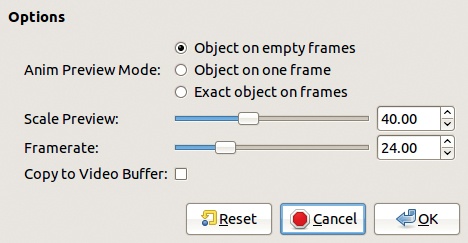
If you don’t get an error message, ANIM PREVIEW opens the dialog shown in Figure 18-31. The animation preview is a scaled-down, multilayer file, and the Playback tool (usually selected via Image: Filters > Animation > Playback) opens automatically.
ANIM PREVIEW MODE can have one of three values:
OBJECT ON EMPTY FRAMES shows the copied layers on blank frames (rather than the target frames) filled with the background color.
OBJECT ON ONE FRAME shows the copied layers on the frame displayed in the preview window of the tool dialog.
EXACT OBJECT ON FRAMES shows a scaled-down version of the final animation.
The third option takes much longer to generate, but the preview more closely approximates the final result.
SCALE PREVIEW changes how much the preview is scaled down. If the setting is 100.0, the preview isn’t scaled down and takes a long time to process. Usually a value between 20 to 40 is ideal. FRAMERATE sets the animation speed in frames per second. COPY TO VIDEO BUFFER, when checked, may produce a smoother animation.
The preview is generated as a new, multilayer animation, which you can delete once you’ve watched it.
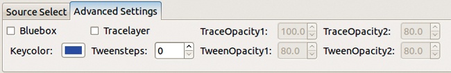
The Move Path dialog has an Advanced Settings tab, shown in Figure 18-32.
When checked, BLUEBOX applies the Bluebox filter to the selected layer, as explained in Bluebox. KEYCOLOR is used with the Bluebox filter and opens the Bluebox dialog.
The TRACELAYER box, when checked, creates an additional layer in all target frames. This layer shows all positions of the moving layer from the beginning of the animation to the previous frame. TRACEOPACITY1 specifies the opacity of this additional layer. TRACEOPACITY2 specifies how much this opacity fades out.
TWEENSTEPS specifies the number of virtual frames, called tweens, that are computed between two consecutive frames and included in a tween layer in the target frame below the stack position of the inserted layer. This tween layer shows the positions of the moving object in all virtual frames. The opacity of this layer is specified by the TWEENOPACITY1 counter and fades out at the older positions, depending on the value of the TWEENOPACITY2 counter.
When you have both a trace layer and a tween layer, the tween layer is invisible so the opacity of the moving object does not increase. These additional layers can be useful for simulating the motion blur of fast-moving objects.