
We’ve already covered two tools in the Image: Video menu—the Morph tool and the Move Path tool. In this section, we’ll discuss the remaining tools. This menu is organized alphabetically, but we’ll discuss the tools in a logical order instead.
Many entries in the Video menu deal with frame manipulations, but quite a few also perform very simple actions.
The Image: Video > Go To menu contains five entries that change the current frame in a multiframe animation. The function of the FIRST FRAME, LAST FRAME, NEXT FRAME, and PREVIOUS FRAME entries are obvious. ANY FRAME opens a dialog where you can select a frame by number.
DELETE FRAMES lets you delete a subrange of frames, beginning at the current frame and ending at the chosen number.
DUPLICATE FRAMES opens the dialog in Figure 18-33. You can choose the starting and ending frame numbers and the number of times to duplicate that range.
EXCHANGE FRAME opens a dialog where you can select the number of the frame to be exchanged with the current one.

FRAME SEQUENCE REVERSE opens a dialog with two sliders, one for the numbers of the FROM FRAME and the other for the TO FRAME. This tool reverses the sequence, so 3–4–5–6–7 becomes 7–6–5–4–3.
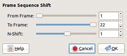
FRAME SEQUENCE SHIFT opens the dialog shown in Figure 18-34. The first two sliders define a frame subrange, and the last cursor, N-SHIFT, specifies the amount of circular shift that will be applied to the subrange. The first frame of the sequence is renumbered N places farther along in the range, and so on, until the last frame, which is N – 1 places farther than the first frame.
FRAMES RENUMBER opens a dialog with two sliders. The first specifies the new number of the first frame, and the second specifies the number of digits of the frame numbers. All the frames are renumbered.
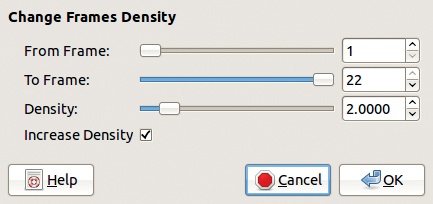
Selecting FRAMES DENSITY opens the dialog shown in Figure 18-35. This dialog allows you to duplicate frames if the density is increased and delete frames if the density is decreased.
The first two cursors are used to select a subrange of the animation. DENSITY can range from 1.0 to 100.0. When INCREASE DENSITY is checked, the density is multiplied by this factor. Otherwise it’s divided by this factor.
Use the Frames Density tool to combine two animations with different frame rates without changing playback speed. For example, you could convert an animation with a frame rate of 8 frames per second to 24 frames per second by choosing a density of 3.0, which will add two copies of every frame to the original animation. If your animation is jerky after you increase the density, try creating onionskin layers (see Onionskin).
Because the Frames Density tool has no undo, work with a copy of your animation so you can return to the original if you make a mistake.
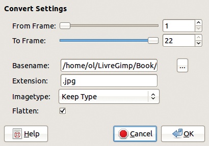
FRAMES CONVERT converts a subrange of the multiframe animation to a different format. The Frames Convert dialog is shown in Figure 18-36. FROM FRAME and TO FRAME set the subrange. The BASENAME specifies where the new frames are stored. The small box at the right opens the file manager dialog that you can use to select the location.

Use the EXTENSION field to select the format that you want to convert the animation to. The IMAGETYPE menu allows you convert the animation to RGB, indexed, or grayscale. Be sure to convert to indexed if you choose GIF as the output format.
When checked, FLATTEN flattens the layers in the output files, which is necessary for most output formats. This tool can be used to convert numerous files at the same time, using many possible input and output formats, as long as the files share a systematic naming scheme.
FRAMES CROP is used to crop all frames of a multiframe animation to a new width and height. Its dialog is shown in Figure 18-37. This tool acts on the animation (not a copy), and the regions of the frames outside the cropped area are discarded.
You can change the width and height of the crop with the NEW WIDTH and NEW HEIGHT fields. The X RATIO and Y RATIO fields also modify the cropping. If the chain to the right of these fields is broken, the X and Y dimensions can be changed independently.

Once you’ve changed the dimensions, you can define what part of the source image remains after cropping using the X and Y fields or using the CENTER HORIZONTAL and CENTER VERTICAL buttons. You can also click and drag in the small rectangular area at the bottom of the dialog.
Use FRAMES RESIZE to change the canvas size of all frames of a multiframe animation. It opens the same dialog as the Frames Crop tool. If the new canvas is smaller than the original, the result is the same as cropping.
FRAMES SCALE changes the scale of all frames in a multiframe animation. Its dialog, shown in Figure 18-38, contains the same fields as the top half of the Frames Crop and Frames Resize dialogs. The algorithm used to scale the frames can be changed in the GIMP Preferences (Image: Edit > Preferences, TOOL OPTIONS entry, DEFAULT INTERPOLATION field).
FRAMES MODIFY is a very powerful tool that you can use to modify selected layers in a subrange of the current multiframe animation. Its dialog is shown in Figure 18-39. The layers are selected based on their name or their number in the layer stack (0 at the top). Under the heading LAYER SELECTION are seven radio buttons, the first six of which use the LAYER PATTERN field just below. Most of the radio buttons are self-explanatory.
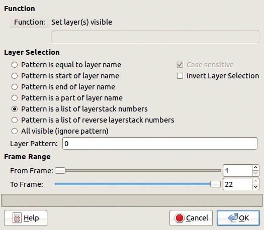

The first four buttons match a string pattern to the exact name of the layer or to a part of its name. The next two choices use a list of layer stack numbers as the pattern. For example, the list “0, 4–6, 8” selects layers 0, 4, 5, 6, and 8. The last choice selects all visible layers.
When you use a string pattern, the CASE SENSITIVE box allows you to distinguish Background from background. In all cases, checking the INVERT LAYER SELECTION box selects all layers that don’t match your criteria.
As usual, select the frame subrange with the FROM FRAME and TO FRAME sliders.
The most complicated part of using the Frames Modify tool is choosing the function to apply to the selected layers and frames.
Figure 18-40 shows the FUNCTION button menus, located at the top of the dialog.
LAYER ATTRIBUTES lets you perform simple operations in the layers, which you can also do by right-clicking the layer name in the Layers dialog.
LAYER MODES contains the 22 blending modes, also selected from the MODE menu in the Layers dialog.
LAYER STACKPOSITION moves layers up and down in the stack.
MERGE LAYERS merges the selected layers into one. The resulting layer can be clipped to the canvas or to the background layer or expanded to the canvas.
SELECTION has several functions. The first four functions (REPLACE, ADD, SUBTRACT, and INTERSECT) take the selection from the frame that was used to open the tool and combine it with existing selections in all frames of the subrange. The remaining functions alter selections in the same ways as the entries in the Image: Select menu.
LAYER MASK includes several functions. The first seven functions are found by selecting the Image: Layer > Mask > Add Layer Mask dialog or by right-clicking the layer name in the Layers dialog. The next three functions are also found in the Image: Layer > Mask menu. The remaining two copy a layer mask from the layer above or below and then apply that mask to all selected layers. The meaning of the other entries in this menu should be clear from their names alone.
Note that some functions require you to enter a name in the field just below the name of the function in the tool dialog.
The function APPLY FILTER ON LAYER(S) opens a dialog when you click OK. This dialog is the same as the one shown in Figure 18-18, and it works the same way. But this tool operates on several layers at the same time, within a subrange of frames.
The function APPLY FILTER ON LAYER MASK (in the LAYER MASK submenu) applies the selected filter to the layer mask instead of the layer itself. If the first selected layer in the first frame in the subrange does not have a layer mask, you’ll get an error. If the selected filter is applied with varying values, the first selected layer in the last frame in the subrange must have a layer mask too. If intermediate layers in intermediate frames have no layer mask, they are skipped while GIMP processes the frame subrange.
To use this powerful tool properly, you should use the same layer stack structure in all frames. We also recommend using meaningful names for the layers—and to do so systematically for all frames.
Several tools in the Video menu, such as FRAMES MODIFY (discussed in the previous section), deal with the layers of the animation frames. In this section, we discuss other tools in the Video menu that alter layers.
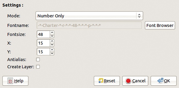
FILENAME TO LAYER creates a new layer in all frames of the subrange that contains the filename. Its dialog is shown in Figure 18-41. In the MODE menu, you can choose to use only the number from the filename, the full name, or a combination of the path and the name. Specify the font in the FONTNAME field with the FONT BROWSER button.
You can also choose the font size and the coordinates of the upper-left corner of the name. Leave the ANTIALIAS box checked. If the CREATE LAYER box is unchecked, the name is written on the active layer.
To use the tool to number all of the frames in a subrange of an animation, you must select the Filename to Layers tool from the Image: Video > Frames Modify menu, using the APPLY FILTER ON LAYER(S) function (called plug_in_gap_renumber).
FRAMES FLATTEN flattens all frames (merges all layers) in the specified subrange. It has a dialog with two sliders, similar to the top part of Figure 18-33.
FRAMES LAYER DELETE deletes one specific layer in all frames of the subrange. It opens a dialog with three sliders, similar to Figure 18-33.
The Image: Video > Layer menu has several entries that can be accessed directly but are much more useful when accessed from the Image: Filters > Filter all Layers tool or the Image: Video > Frames Modify tool.
Two tools can be used to convert a multilayer animation to a multiframe one, and vice versa.
SPLIT IMAGE TO FRAMES must be opened from a multilayer image. Its dialog appears in Figure 18-42. You can’t choose names for the new frames or their position in the folder hierarchy. To save the new frames in a particular folder, place the source image in that folder before splitting it into frames.
The EXTENSION is XCF, by default, and it is the safest extension to use, but you can enter any format supported by GIMP. The dialog has four checkboxes that, when checked, do the following:
INVERSE ORDER starts with the first frame (the top layer) instead of the bottom frame.
FLATTEN flattens the new frames, and any transparent areas are filled with the background color .
ONLY VISIBLE ignores invisible layers. When unchecked, all layers generate a frame, regardless of their visibility.
COPY PROPERTIES copies the channels, paths, and guides existing in the image to all the frames. When unchecked, these properties are ignored.

Finally, the DIGITS counter specifies the number of digits contained in the numeric part of the frame names.
FRAMES TO IMAGE creates a multilayer image from frames, so it must be opened from a multiframe animation. Its dialog is shown in Figure 18-43.
The first two sliders specify the subrange of the frames that will be used to build the multilayer image. The LAYER BASENAME field lets you name the layers. By default, all layer names begin with frame_, but you can change that to any string. The number signs in the square brackets will be replaced by the frame number, but you can change the number of digits. The duration of each layer is 24 images per second, by default, but you can change that as well.
The new layers are created by merging the layers in the source frames (unless FLATTENED IMAGE is selected). LAYER MERGEMODE lets you choose how the image size is determined.
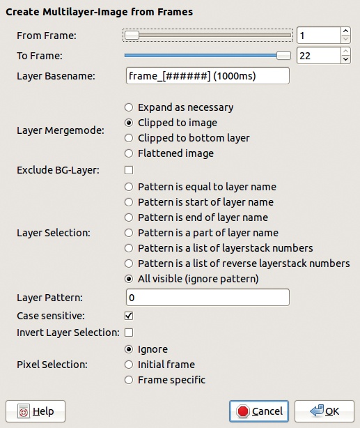
EXPAND AS NECESSARY expands the image size to fit around all layers.
CLIPPED TO IMAGE clips the layers to the image size.
CLIPPED TO BOTTOM LAYER clips the image to the size of the bottom layer of the source.
FLATTENED IMAGE creates the new layer by flattening rather than merging the source layers, so the resulting layer, which is the same size as the image, has no transparent part.
When checked, EXCLUDE BG-LAYER excludes the background layer from all source frames. When unchecked, this layer is handled like any other.
LAYER SELECTION determines how the source layers are selected. For the first four options, the LAYER PATTERN field is a character string, which should match at least part of the name of the layers you want to select. The next two options require a list of layer numbers (“1, 3–5, 9” for example). Layers are numbered from zero, beginning at the top layer (or at the bottom layer if the third option is chosen). The final option selects all visible layers. If CASE SENSITIVE is checked, the case of the string must match for the layer to be selected. All of these options can be inverted by checking INVERT LAYER SELECTION.
PIXEL SELECTION specifies how an existing selection is handled. IGNORE ignores all selections in the source frames. INITIAL FRAME uses the selection from the first frame of the subrange and applies it to all frames. The unselected areas are transparent, and the layer shape is determined by the selection. FRAME SPECIFIC uses the selection in each selected frame.
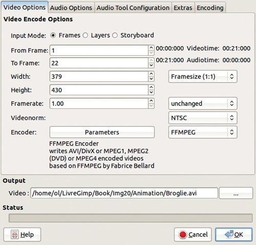
MASTER VIDEOENCODER converts multiframe or multilayer animations into a specific video file encoding. Its dialog is shown in Figure 18-44. You can also use a storyboard with this option, as explained in Storyboard.
OUTPUT allows you to name the output file. The extension is added by GIMP, depending on the chosen encoder. The button to the right opens the local file manager. The STATUS field shows the conversion progress.
The first tab in this dialog is VIDEO ENCODE OPTIONS. You can select the INPUT MODE; however, the tool automatically chooses one based on the source file. The next two fields define the subrange of frames or layers to be used as the source.
WIDTH and HEIGHT specify the size, in pixels, of the resulting video frames. The menu to the right lists a set of standard sizes.
FRAMERATE specifies the number of frames per second. The menu to the right has a set of standard rates.
The VIDEONORM menu contains the usual norms (NTSC, PAL, SECAM), which generally depend on the country in which the video will be broadcast.
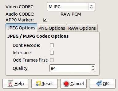
ENCODER is operational only after you choose an encoder plug-in in the box to the right. For example, Figure 18-45 shows the parameters of the AVI1 encoder.
The remaining tabs in the Master Videoencoder dialog deal with audio options and the audio tool configuration, which is beyond the scope of this book.
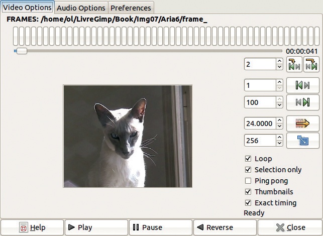
Use PLAYBACK to preview a multiframe animation (but not a multilayer one). It cannot play MPEG or AVI files. You can open Playback via Image: Video > Playback, but you may also open it from the VCR Navigator (discussed next) or from the Storyboard dialog (see Storyboard).
The lower part of the Playback dialog (Figure 18-46) contains the standard play forward, pause, and play backward buttons. ![]() clicking one of the two play buttons creates a “snapshot” image, which is a small multilayer animation containing all the frames that have been played up to this point. When an animation is playing, you can jump to the first, middle, or last frame by clicking the pause button with the left, middle, or right mouse buttons, respectively.
clicking one of the two play buttons creates a “snapshot” image, which is a small multilayer animation containing all the frames that have been played up to this point. When an animation is playing, you can jump to the first, middle, or last frame by clicking the pause button with the left, middle, or right mouse buttons, respectively.
The top of the Playback dialog contains a set of 50 rectangles, which are the GO array, an array of the 50 current frames. Move the pointer over the array to display the frames in real time. You can stop at a particular point in an animation or play the animation at a different speed. Clicking one of the rectangles displays that frame in the source animation window. If the animation is larger than 50 frames, the GO array is a subrange of frames, and by moving the pointer to one side or the other, you can change the subrange contained in the array. The mouse scroll wheel can also move the animation frames.
The buttons and counters at the right side of the dialog let you display information on the current frame and set a subrange of the animation to play. Two counters below the current frame counter, or the two buttons at the right of the counter, are used to select a range. ![]() click one of these buttons to make the corresponding frame the current image.
click one of these buttons to make the corresponding frame the current image.
You can also set the frame rate and the size (in pixels) of the preview window, which also changes when you resize the dialog.
The five boxes at the bottom right of the dialog control playback and are mostly self-explanatory. Check THUMBNAILS once you’ve seen the animation because that lets you reuse the small images generated. Use EXACT TIMING to skip frames and save time in an animation’s playback.
VCR NAVIGATOR lets you perform simple edits on an animation or play it back. The VCR Navigator dialog is shown in Figure 18-47. In the middle is a scrollable list of frame thumbnails. You can see the frame numbers, as well as the time elapsed from the beginning of the animation. FRAMERATE and TIMEZOOM let you control the frequency and timing of the frames, and the result is immediately visible in the thumbnail area.
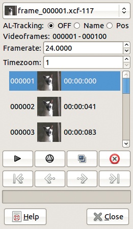
At the top of the VCR Navigator is the animation selector. Next is AL-TRACKING (Active Layer Tracking). Active Layer Tracking finds a layer in the newly loaded frame that matches the active layer of the previous frame and sets that layer as the active one. Three options are available:
OFF disables Active Layer Tracking.
NAME compares the layer names from left to right and chooses the layer that best matches.
POS uses the layer’s stack position; onionskin layers are not counted.
In the thumbnail area, you can select frames: A single click selects one frame; ![]() -click adds (or removes) the frame to the selected frames; and
-click adds (or removes) the frame to the selected frames; and ![]() -click selects all layers between the previous and the current layer. Right-click to open a simple editing menu (copy, cut, paste, and so on).
-click selects all layers between the previous and the current layer. Right-click to open a simple editing menu (copy, cut, paste, and so on).
Below the thumbnails are two rows of buttons. The playback button opens the Playback tool. ![]() -click it to use the selected frames to build a temporary multilayer animation and then open the Playback tool.
-click it to use the selected frames to build a temporary multilayer animation and then open the Playback tool.
The next button (a triangle in a circle) updates only those thumbnails that are out of date; press ![]() to update all thumbnails. The next button duplicates the selected frames, and the last one deletes them. The lower row of buttons lets you navigate through the frames of an animation.
to update all thumbnails. The next button duplicates the selected frames, and the last one deletes them. The lower row of buttons lets you navigate through the frames of an animation.
The menu Image: Video > Split video into frames contains two entries.
MPLAYER-BASED EXTRACTION is the best tool for converting a video file to a multiframe animation, but it works only if you have MPlayer installed. MPlayer is free software, available for all platforms. See http://www.mplayerhq.hu/ for more information.
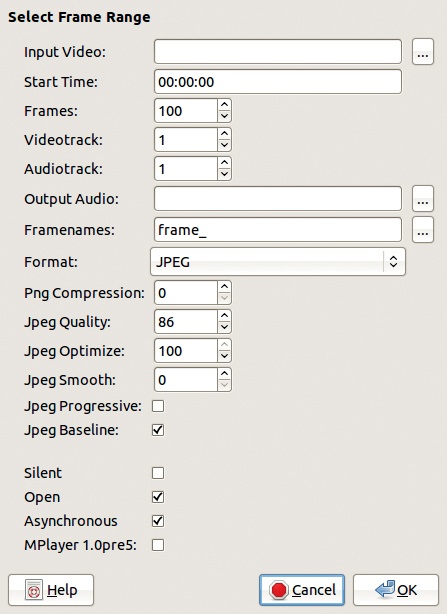
The MPlayer-based extraction tool, shown in Figure 18-48, supports many input formats. The most useful fields are as follows:
INPUT VIDEO is where you can enter the name of the input video or click the button on the right to browse for the file.
START TIME is the place in the video where you want to begin extracting, entered in hours:minutes:seconds.
FRAMES sets the number of frames to extract.
VIDEOTRACK and AUDIOTRACK are useful if the input video file is multitrack, but that isn’t very common. Enter 0 to ignore the audio or video track.
FRAMENAMES sets the base name of the new frames. To use the file navigator, click the button on the right.
FORMAT lets you choose JPEG, PNG, or XCF (generally the best choice). Below that you can adjust the compression or optimization, depending on the output format.
SILENT, if checked, ignores any audio track.
OPEN opens the first frame once the extraction is finished.
ASYNCHRONOUS, when checked, sets MPlayer to run asynchronously, so it doesn’t block other processes running on the computer.
The frames of the input video are first converted to PNG and then to the chosen output format, which is normally XCF. Because the frames are processed twice, and a one-minute video sequence contains 1440 frames, these conversions can take half an hour or more.
The other entry in the Image: Video > Split video into frames menu is EXTRACT VIDEORANGE. When no additional video software is installed, this tool can only process an MPEG input file. Its dialog is shown in Figure 18-49. At the top of the dialog, choose the input file and then the range, either using the counters FROM FRAME and TO FRAME or the extended dialog that opens if you click VIDEO RANGE, as shown on the right of Figure 18-49.
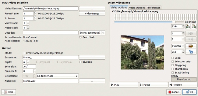
You can generally leave the remaining fields in the input portion of the Extract Videorange dialog set at the defaults. In the OUTPUT section, you can choose whether to generate a multilayer or multiframe animation. You can also choose the base name of the frames, the number of digits, the extension (and format), and the number of the first frame. The audio track is extracted into a WAV file.
Bluebox uses a technique often called blue screen in cinematography. It’s also called chroma key, color keying, or color-separation overlay. Basically, a scene is filmed with the actor(s) in front of a blue (or green) screen. The blue (or green) part of the video frame is then replaced with a different background. This technique can also be used to make an actor appear more than once in the same scene.
The Bluebox dialog is shown in Figure 18-50. Bluebox is actually a filter and works best when opened through the Move Path tool because it operates on a single layer. You can also open it through the Frames Modify tool from the Apply filter on layer(s) function.
KEYCOLOR chooses the color of the background to removed. You can choose any color via the Color chooser. Pixels similar to this chosen color are made transparent according to the threshold setting.
The THRESHOLD MODE can be RGB (three values), HSV (three values), VALUE (one value), or ALL (HSV and RGB combined, six values). These thresholds range from 0.0 to 1.0, where 0.0 only targets the exact color and 1.0 makes the widest range of colors transparent. The ALPHA TOLERANCE also changes how much of the background becomes transparent.
SOURCE ALPHA sets a maximum Alpha value to prevent transparent pixels from becoming part of the selection. TARGET ALPHA specifies the transparency of the selected pixels after the transformation. You can feather (smooth) the edges of the selection and shrink or grow it.
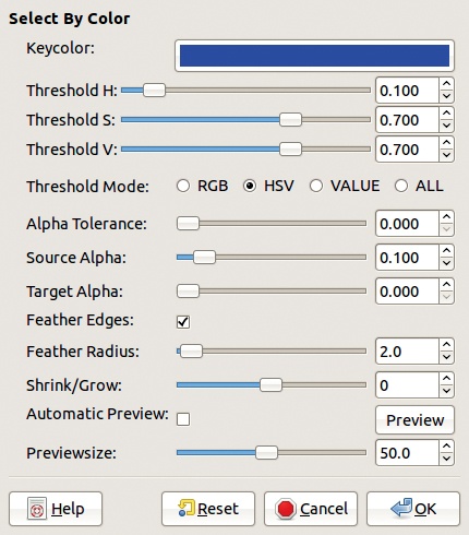
You can also adjust the size of the preview window, which is useful because this filter has no undo capability.
An onionskin layer is used to show the previous (or next) frame of an animation in the current frame. This is useful when painting moving characters, for example. The onionskin is automatically deleted when you move on to the next frame.
Onionskin layers can also be used for smoothing very fast movement to simulate motion blur, as we discussed in Manipulating Frames. Onionskin layers behave like normal layers for the most part, but special tools are available for doing some things like toggling visibility.
By default, onionskin layers are built by merging the visible layers of the previous frame without the background or any other onionskin layers. They are usually placed above the background layer in the current frame.
The Image: Video menu has a submenu called ONIONSKIN. CONFIGURATION, the main entry, opens the dialog shown in Figure 18-51.
LAYER SELECTION lets you choose the layers to be selected and is similar to the Frames Modify tool (see Modifying Frames). An additional field lets you ignore a number of background layers.
The large field displaying the name of the current multiframe animation is actually a button used to set the video’s parameters. The two boxes below it are used to create or delete onionskins automatically when you select the tool from the VCR Navigator tool or when you move to the next frame using File: Video > Go To > Next Frame. When both boxes are checked, onionskins are automatically added when you load a frame and deleted when you save the frame.
The top of the dialog, ONIONSKIN SETTINGS, specifies how the layers from the previous frames are copied. FRAME REFERENCE refers to the source frame number from which the onionskin layer is copied. If the frame reference is –1, it means that the first onionskin layer will be copied from the previous frame, the second from the frame before that, and so on. A positive frame reference means that the onionskin is made up of frames that come after the current frame.
REFERENCE MODE specifies the way neighboring frames are used. In Normal mode, the delta provided by FRAME REFERENCE is used in one direction only. This delta value determines which onionskin layers are built and copied in the current frame. In Bidirectional (single) mode, this delta is used alternately in both directions, but a given offset is used only once, as in the sequence –1, +2, –3, +4,.... In Bidirectional (double) mode, each delta is used twice, as in the sequence –1, +1, –2, +2, –3, +3,...

You can also specify the number of onionskin layers to generate, their stack position, and their opacity.
Clicking OK adds the onionskin layers, whereas clicking DELETE removes them. CLOSE uses the parameters to define the settings throughout the current animation without generating an onionskin layer.
Once the settings are defined, the remaining entries in the Image: Video > Onionskin menu let you make global changes to the selected frames. You can create the onionskin layers or replace layers that you created previously. You can also delete specified onionskin layers or toggle their visibility.
The Onionskin tools are designed to work with the VCR Navigator or the Image: Video > Go To operations. When you move between frames, the actions specified by the AUTO boxes (if checked) are performed automatically. When both AUTO boxes are checked, the frame is saved after deleting the onionskin, and a new onion-skin is created in the next frame according to the parameters saved in the Image: Video > Onionskin > Configuration dialog.
A storyboard is a text file that describes how to assemble video clips, images, and audio files to build a single output video file. Storyboards are useful for creating and cutting long video sequences. In fact, the Storyboard Editor, together with its accompanying tools, provides a means for editing a video sequence by assembling video clips, multiframe animations, and single images. It does not provide as many features and capabilities as more specialized video-editing tools (such as Kden-live at http://www.kdenlive.org/ or Cinelerra at http://cinelerra.org/), but it does allow you to use GIMP’s image-editing capabilities to work on individual frames.
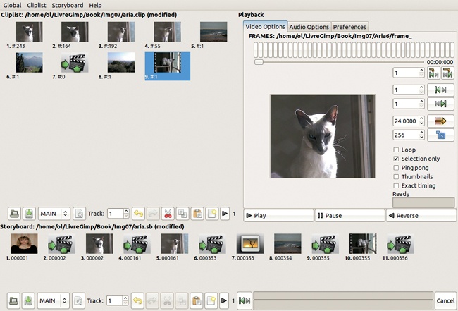
Selecting Image: Video > Storyboard opens the dialog in Figure 18-52. The right side of this dialog is similar to the Playback dialog and is fairly intuitive. The left side is divided into the Cliplist and the Storyboard itself. The menu bar at the top of the window contains two identical menus (CLIPLIST and STORYBOARD) for the two sections. In the GLOBAL menu, check the VIDEOTHUMBNAILS button to view thumbnails of the Cliplist and Storyboard. The PROPERTIES entry opens a dialog where you can choose the layout of the Cliplist and Storyboard sections, including the size of the thumbnails.
To use the Cliplist or Storyboard, you first must choose a video or animation file. To begin a new project, select Storyboard > New. In the dialog that appears, select the characteristics of the video animation you plan to build and enter the name of the storyboard file. Also select Cliplist > New. Its dialog is the same, but you must choose a different name for the file. Both menus contain additional entries that are fairly self-explanatory.

To add a clip, select Cliplist > Create Clip, which opens the dialog shown in Figure 18-53. You can load frames or layers from another animation and set several parameters for this new clip. Note that if the new clip is significantly different from the video that it’s added to, the frames may be deformed.
A single image can also be used as a new clip. You can even drag and drop an image from a file manager.
After a clip is selected, it’s displayed as a thumbnail in the PLAYBACK section of the Storyboard Editor dialog. You then choose the frame range to be used as a clip and add it to the Clip-list by clicking the first button on the right. The second button adds the inverse range.
Once you have clips in the Cliplist, add them to the Storyboard by
using the CUT, COPY, and PASTE buttons at the bottom of the Cliplist to arrange the clips in sequence
using the CUT, COPY, and PASTE buttons in the Storyboard to copy and arrange clips
clicking the play button at the bottom right of the Cliplist to play the sequence of clips or only the selected clips
double-clicking a clip thumbnail to play it
right-clicking a clip thumbnail to change its properties (Figure 18-53)
Playing a clip or clip sequence is useful when selecting a subrange of frames and defining a new clip. Pasted clips are added after the last selected clip or at the end of the sequence.

The Cliplist and Storyboard menus also allow you to create a transition. This menu entry opens the dialog shown in Figure 18-54. Create transitions by changing the opacity of frames, scrolling frames, or zooming. You can also combine these effects.
Once you’ve finished building a storyboard, you can save it as a text file. These files use a well-defined syntax, and you can modify them with a text editor if you know the syntax.