The Toolbox contains nine local transformation tools, as shown in Figure 16-34. You can also find them in the Image: Tools > Transform Tools menu, which is shown in Figure 16-35. Local transformations act only on an object or region of an image or layer. Keyboard shortcuts also exist for these tools—and for almost all the other tools in the Toolbox. As we present each tool, we show the Toolbox icon, the keyboard shortcut, and the tool pointer.


All the tools in the Image: Tools > Transform Tools menu (except Align and Crop) operate on the current layer, the current selection, or the current path but not on multiple layers simultaneously. Figure 16-36 shows the options for the Move tool. The top row of buttons allows you to decide whether the tool acts on the current layer, the current selection (rather than the selected layer content), or the current path. These buttons are, in fact, the only way to switch among the layer, selection, and path when using a tool from the Image: Tools > Transform Tools menu. You make this choice in the individual options for each tool, and your choice does not propagate to the other transformation tools. But changes to the parameters do remain in place for a specific tool until you restart GIMP, so if you use GIMP for a long period of time and change the settings for one of the transformation tools, check the settings before using the tool again. Figure 16-37 shows the result of moving the current selection (which was built with Image: Layer > Transparency > Alpha to Selection). The selection, rather than its contents, is moved.


The Rotate, Scale, Shear, and Perspective tools share the same set of options. Although the options shown in Figure 16-38 are for the Rotate tool, the only difference is the dialog’s name, which appears in bold at the top, and, in some cases, the presence of a checkbox at the bottom of the dialog, which is discussed later. In this section, we examine all these options in turn.

The DIRECTION can be NORMAL (FORWARD), in which case the image moves with regard to the canvas, or CORRECTIVE (BACKWARD), which causes the grid to move with regard to the image. The CORRECTIVE (BACKWARD) option works well for correcting object deformities within an image, such as warped perspective. When using this option, align a grid with the warped object, like we did in The Perspective Tool.
The INTERPOLATION menu contains four possible algorithms to compute new pixels from old ones. Although NONE is the fastest, the result is very poor, as shown in Figure 16-39. The other three methods do a reasonably good job, but the most processor intensive, SINC (LANCZOS3), yields the best result. Unless your computer is extremely slow or the image being processed is huge, choose SINC (LANCZOS3).
The CLIPPING menu (Figure 16-40) specifies what happens if the layer is larger after a transformation.

ADJUST enlarges the layer to the size of its new contents, as shown in Figure 16-41. If the layer no longer fits in the canvas, use Image: Image > Fit Canvas to Layers to enlarge the canvas.
CLIP clips the layer’s contents to the layer’s boundaries, as shown in Figure 16-42.
The other two choices, CROP TO RESULT and CROP WITH ASPECT, work like CLIP and ADJUST, respectively, but they remove any border with no content, a situation that may occur after the transformation. Figure 16-43 shows the case of CROP TO RESULT.


If the SHOW IMAGE PREVIEW button is unchecked, when you click and drag the image to operate the transformation, the transformed part of the image is not shown, and you see only an outline or some guides. In Figure 16-44, the button is unchecked and there are no guides.
If the SHOW IMAGE PREVIEW button is checked, you can choose the opacity of the image preview, which can help when you want a very precise transformation. For example, in Figure 16-45, the opacity of the preview was set to 50%.

The GUIDES menu (Figure 16-46) offers a number of choices:
When NO GUIDES is selected, only an outline of the layer appears while the transformation is in progress. The image appears unchanged until you accept the transformation. See Figure 16-44 and Figure 16-45.
The next five choices are the same as for the Rectangle Select tool, and they are described in The Rectangle Select Tool. For example, Figure 16-47 shows the case of Diagonal lines, with an image preview.
When LINE SPACING is selected, a grid is displayed over the layer, as shown in Figure 16-48. You can change the spacing of grid lines by using the field at the bottom of the options dialog, as shown in Figure 16-38.
You can combine the guides and a visible image preview, as shown in Figure 16-49.

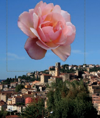
The Move tool is the simplest transformation tool. Select it by pressing ![]() or clicking its icon in the Toolbox. Its icon and pointer are shown in Figure 16-50. Once you select the Move tool, click and drag a layer, selection, or path to move it. In the tool options (see Figure 16-36), you can choose whether to move the active layer, selection, or path, or you can select the object to be moved by clicking it. In the present example, we wanted to move the rose, so we were careful to click a nontransparent pixel so as not to accidentally move the underlying layer instead. If the image has a guide, you can move it if you click close enough to it (the guide turns red). Toggle between the two options by pressing the
or clicking its icon in the Toolbox. Its icon and pointer are shown in Figure 16-50. Once you select the Move tool, click and drag a layer, selection, or path to move it. In the tool options (see Figure 16-36), you can choose whether to move the active layer, selection, or path, or you can select the object to be moved by clicking it. In the present example, we wanted to move the rose, so we were careful to click a nontransparent pixel so as not to accidentally move the underlying layer instead. If the image has a guide, you can move it if you click close enough to it (the guide turns red). Toggle between the two options by pressing the ![]() key.
key.
If a selection exists, but LAYER MOVE mode is active, temporarily shift to SELECTION MOVE mode by pressing ![]() before making a move.
before making a move.
Use the arrow keys on the keyboard to move the active layer or path. Each key press moves the layer or path by 1 pixel in the corresponding direction. If you press and hold ![]() , each key press moves the layer or path by 50 pixels.
, each key press moves the layer or path by 50 pixels.
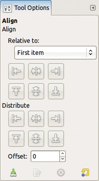
Select the Align tool by pressing ![]() or clicking its icon in the Toolbox. Its icon and pointer are shown in Figure 16-51, and its options dialog is shown in Figure 16-52. In this case, the buttons in the options dialog are actually used to operate the tool.
or clicking its icon in the Toolbox. Its icon and pointer are shown in Figure 16-51, and its options dialog is shown in Figure 16-52. In this case, the buttons in the options dialog are actually used to operate the tool.

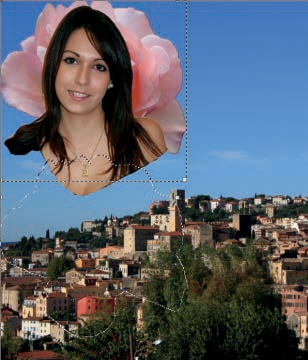
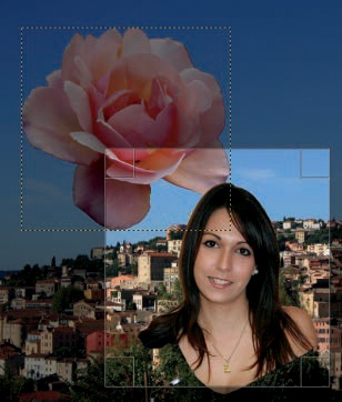
We used the image in Figure 16-53 to demonstrate the Align tool. The Layers dialog for this image is shown in Figure 16-54. The outline of the middle layer, which contains the rose, is visible in Figure 16-53. We selected the portrait in the top layer with the Scissors Select tool and then cut and pasted it into the image as a new layer with a transparent background. A selection, built around the rose and then moved down in the image, is also present.


When you select the Align tool, the mouse pointer changes to a hand. Click in the image to select the object (i.e., a layer) that you will move, called the source. To select several objects, either ![]() -click all the objects after the first one or click and drag to build a rectangle around all the objects. The selected objects are indicated by small squares in the corners of the enclosing rectangle.
-click all the objects after the first one or click and drag to build a rectangle around all the objects. The selected objects are indicated by small squares in the corners of the enclosing rectangle.
When you select at least one object, the buttons in the options dialog become active. Choose the alignment target, which is the object that the selected objects will be aligned to. Six choices are located in the RELATIVE TO menu, which is shown in Figure 16-55:
FIRST ITEM: The target is the first selected object. If only one object is selected, or if the selection is a rectangle, this choice behaves the same as IMAGE.
IMAGE: The target is the image itself. In Figure 16-56, we selected the portrait layer and clicked the middle button in the lower row.
SELECTION: The target is an invisible rectangle around your selection whose height and width match that of the selection exactly. For example, in Figure 16-57, we clicked the middle button in both button rows to center the portrait in the middle of our selection, the outline of the rose, which is visible in Figure 16-53.
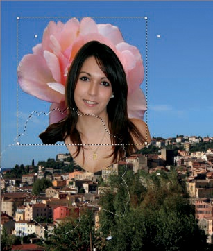
ACTIVE LAYER: The idea is simple, as demonstrated in Figure 16-58. Again, we clicked the two middle buttons to position the portrait in the center of the rose.
ACTIVE CHANNEL: This option allows you to align to a selection made previously that’s saved in a channel.
ACTIVE PATH: This option allows you to align to a path.


The second set of buttons, labeled DISTRIBUTE, act based on the OFFSET field setting. In Figure 16-59, we selected the two upper layers as the source and aligned them along the left and top edges of the image. In Figure 16-60, we did the same thing but used the DISTRIBUTE buttons and an offset of 100 pixels.
To select the Crop tool, press ![]() or click its icon in the Toolbox. Its icon and pointer are shown in Figure 16-61, and its options are shown in Figure 16-62. This tool removes any parts of the image that are outside a selected rectangle. Build the rectangle the same way you would build a selection with the Rectangle Select tool. Normally the selected area is highlighted, as shown in Figure 16-63. When you’re satisfied with the selection, click inside it or press
or click its icon in the Toolbox. Its icon and pointer are shown in Figure 16-61, and its options are shown in Figure 16-62. This tool removes any parts of the image that are outside a selected rectangle. Build the rectangle the same way you would build a selection with the Rectangle Select tool. Normally the selected area is highlighted, as shown in Figure 16-63. When you’re satisfied with the selection, click inside it or press ![]() to crop the image.
to crop the image.
The Crop tool has several options.
The CURRENT LAYER ONLY checkbox allows you to crop just the current layer, rather than the whole image. The selection automatically stops at the layer’s boundary, as shown in Figure 16-64.
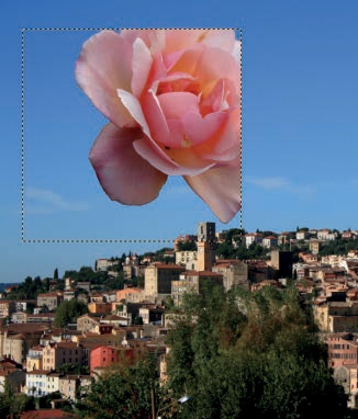
The ALLOW GROWING checkbox allows the selection to cross the boundaries of the image or the layer. For example, in Figure 16-65 both the ALLOW GROWING and the CURRENT LAYER ONLY checkboxes are checked. Figure 16-66 shows the result. Notice that the boundaries of the flower layer are extended based on the selection.
The EXPAND FROM CENTER checkbox works as it does with the selection tools: The first click will be the center of the selection, rather than a corner. Note, however, that you can’t toggle this option with the
 key, as you can with the selection tools.
All the remaining fields—FIXED, POSITION, SIZE, HIGHLIGHT, AUTO SHRINK, SHRINK MERGED, as well as the use of guides—work in the same way as they do with the Rectangle Select tool, described in The Rectangle Select Tool.


To select the Rotate tool, press ![]() or click its icon in the Toolbox. Its icon and pointer appear in Figure 16-67. Note that you can also access the Rotate tool via Image: Layer > Transform > Arbitrary Rotation. Almost all of its options have been discussed previously (see Figure 16-38). Only one option is specific to this tool: the 15 DEGREES checkbox, which you can toggle by pressing
or click its icon in the Toolbox. Its icon and pointer appear in Figure 16-67. Note that you can also access the Rotate tool via Image: Layer > Transform > Arbitrary Rotation. Almost all of its options have been discussed previously (see Figure 16-38). Only one option is specific to this tool: the 15 DEGREES checkbox, which you can toggle by pressing ![]() . When active, this option forces the rotation angle to be a multiple of 15°.
. When active, this option forces the rotation angle to be a multiple of 15°.


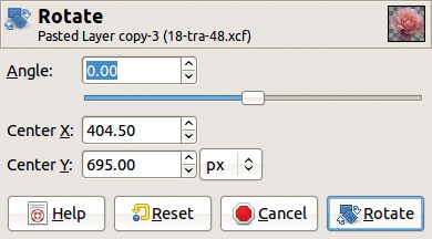
After selecting the tool, click the image. The dialog shown in Figure 16-68 pops up. The rotation center is initially the center of the object being rotated, but you can change it by clicking and dragging. You can change the angle in three ways: Drag the object in the Image window; move the slider in the dialog; or adjust the number displayed in the ANGLE field by typing, using the mouse wheel, or clicking the small arrows. Click the ROTATE button to finalize the rotation.
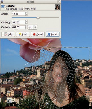
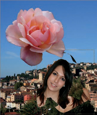
If a selection is active, only its content is affected by the transformation tools. Figure 16-69 shows a rotation in progress: Only the region of the portrait layer within the selection is being rotated. The result is shown in Figure 16-70. The selected pixels from the portrait layer are now a floating selection.
Select the Scale tool by pressing ![]() or clicking its icon in the Toolbox. Its icon and pointer are shown in Figure 16-71. Although the Scale tool appears to do the same thing as Image: Layer > Scale Layer, it’s actually rather different. Image: Layer > Scale Layer acts on the entire image, not on a selection or path, and it doesn’t offer a preview or the corrective mode option.
or clicking its icon in the Toolbox. Its icon and pointer are shown in Figure 16-71. Although the Scale tool appears to do the same thing as Image: Layer > Scale Layer, it’s actually rather different. Image: Layer > Scale Layer acts on the entire image, not on a selection or path, and it doesn’t offer a preview or the corrective mode option.
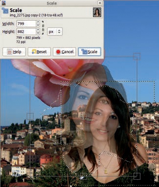
Figure 16-72 shows the scaling process with this tool. The current layer is the portrait layer, which has an active selection. The preview is the image, with the opacity of the region being scaled set to 60%. The center of the scaled area is marked with a circle and a cross, and you move it by clicking and dragging. Press ![]() to scale the selection, which then becomes a floating selection.
to scale the selection, which then becomes a floating selection.
The Scale tool is surprisingly versatile. Try the following:
Click and drag the circle at the center of the area being scaled to move it around in the image, just as the Move tool does.
Click and drag any other part of the selection or layer to adjust the scaling amount.
Keep the current aspect ratio by clicking the checkbox in the tool options and the chain in the tool’s dialog or by pressing the
key. If you drag the handles on the sides, only one dimension is changed, and the aspect ratio is maintained.
Select the Shear tool by pressing ![]() or clicking its icon in the Toolbox. Its icon and pointer are shown in Figure 16-73. Its options are the same as those shown in Figure 16-38. It’s impossible to shear both vertically and horizontally at the same time. The tool sets the direction of a shearing based on the direction that you drag the mouse after the first click. To shear, click and drag the selection. Figure 16-74 shows the transformation in progress. The preview is opaque, but in the figure, the opacity of the layer being sheared was reduced to 50%. The selection that’s acted on by this tool becomes the current selection, and any previous selection is dismissed.
or clicking its icon in the Toolbox. Its icon and pointer are shown in Figure 16-73. Its options are the same as those shown in Figure 16-38. It’s impossible to shear both vertically and horizontally at the same time. The tool sets the direction of a shearing based on the direction that you drag the mouse after the first click. To shear, click and drag the selection. Figure 16-74 shows the transformation in progress. The preview is opaque, but in the figure, the opacity of the layer being sheared was reduced to 50%. The selection that’s acted on by this tool becomes the current selection, and any previous selection is dismissed.

To select the Perspective tool, press ![]() or click its icon in the Toolbox. Its icon and pointer are shown in Figure 16-75. Its options are the same as those presented in Figure 16-38.
or click its icon in the Toolbox. Its icon and pointer are shown in Figure 16-75. Its options are the same as those presented in Figure 16-38.
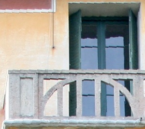
Figure 16-76 shows the Perspective tool being used on an image with a perspective that’s slightly skewed. For this type of adjustment, Corrective direction mode works best because you can align the grid’s vertical and horizontal lines to those of the building.
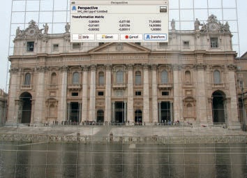

The result appears in Figure 16-77. Although the adjustment helped, the image is no longer rectangular, and the lens distortion of the camera is visible.
You can select the Flip tool by pressing ![]() or clicking its icon in the Toolbox. Its icon and pointer are shown in Figure 16-78. You can choose whether to flip horizontally or vertically (
or clicking its icon in the Toolbox. Its icon and pointer are shown in Figure 16-78. You can choose whether to flip horizontally or vertically (![]() toggles between these) and whether to flip the current layer, selection, or path. As with previous tools, if a selection exists in the current layer, flipping the layer flips only the part that’s within the selection. Figure 16-79 shows the image after a selected part of the rose layer was flipped horizontally. As with the other transformation tools, a floating selection is built to contain the flipped pixels.
toggles between these) and whether to flip the current layer, selection, or path. As with previous tools, if a selection exists in the current layer, flipping the layer flips only the part that’s within the selection. Figure 16-79 shows the image after a selected part of the rose layer was flipped horizontally. As with the other transformation tools, a floating selection is built to contain the flipped pixels.

The only difference between the Flip tool and those tools found in Image: Layer > Transform is that this tool allows you to flip a selection or a path instead of just the layer or a portion of the layer.
The Cage Transform tool was added to GIMP in version 2.8. Its icon and pointer are shown in Figure 16-80, and its options are shown in Figure 16-81.
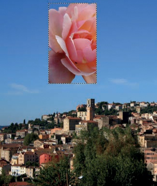
Use the Cage Transform tool to distort an object. A cage is a polygon built around a target portion of the image. Move the corners of the cage to distort the object within. Our example figure has two layers, one containing the city and one containing the rose. Select the rose layer and enlarge it to the same size as the image, using Image: Layer > Layer to Image size.
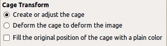
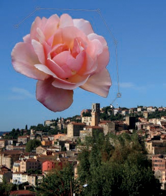
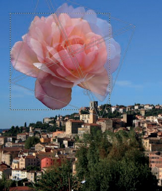
Select the Cage Transform tool and make sure the first option, CREATE OR ADJUST THE CAGE, is checked. Build the cage by clicking around the rose. You can move each point after placing it, but you can’t delete points, and you can move only the most recently placed point. But once the cage is closed and GIMP has worked for a moment, you can go back and add points or move existing points. This tool has no undo capability, so if you make a mistake, you’ll have to start over by temporarily switching to another tool. When you’re satisfied, finalize the cage by clicking the first point. Figure 16-82 shows the cage being built.
Once the cage is finalized, two successive on-canvas messages appear briefly, indicating that GIMP is processing. Then the options dialog changes, and DEFORM THE CAGE TO DEFORM THE IMAGE is selected by default. However, you can change it back to CREATE OR ADJUST THE CAGE. This allows you to add a point by clicking and dragging in a segment or to delete a point by clicking it and pressing ![]() . After that, you can click DEFORM THE CAGE TO DEFORM THE IMAGE to go to the next step.
. After that, you can click DEFORM THE CAGE TO DEFORM THE IMAGE to go to the next step.
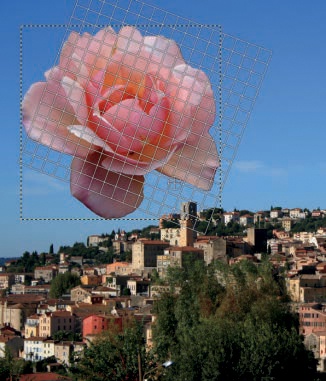
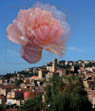
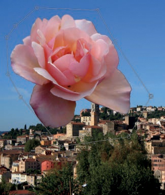
Now you can move the points of the cage to deform the rose. But the computations involved take a while, and you have to wait for the transformation to finish before moving another point. Figure 16-83 shows the result after moving the bottom points of the cage. To finish the transformation, press ![]() . To cancel the transformation, change to another tool.
. To cancel the transformation, change to another tool.
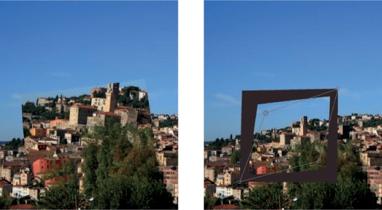
When used properly, this tool can generate smooth, natural transformations. It works best on multilayer images, particularly on layers that contain objects and transparent background pixels, as with the rose we just transformed. But this tool does a poor job on objects that are part of an image because the limits of the cage are sharp and visible, and the cage transformation is only defined on the interior of the cage. Figure 16-84 (left) shows the result of building a rectangular cage in the middle of an image and then enlarging it. Shrinking the cage results in empty geometric spaces. If you check the FILL THE ORIGINAL POSITION OF THE CAGE WITH A PLAIN COLOR option, these spaces are filled with the color of the first point, as shown in Figure 16-84 (right). If the option is unchecked, these spaces show the original contents of the corresponding areas of the image.