The first seven tools in the Toolbox (if they’re in the default order) are the selection tools, shown in Figure 13-8.
Like most tools initially present in the Toolbox, and like most other tools in general, selection tools have options, so keep the options dialog open and docked at the bottom of the Toolbox.
If you’ve accidentally closed it, just select Image: Windows > Dockable dialogs > Tool Options, double-click the tool icon, and drag the dialog that appears to the bottom of the Toolbox.
In the following section, we go through all the options for each of the selection tools. But some of these options are common to all tools, and we describe those just once—right here at the beginning. Figure 13-9 shows common selection options when the Free Select tool is active.
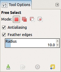
The MODE option contains four ways to combine a new selection with an existing selection:
Replace the existing selection with the new one. This is the default mode. The previous selection is discarded when a new selection is made.
Add the new selection to the current one. Pressing and holding
 before using the selection tool activates this mode even if you haven’t checked it. Newly selected pixels are added to the pixels that were already selected. During construction of the selection, the mouse pointer is accompanied by a + sign.
Subtract the new selection from the current one. Pressing
 before using a selection tool activates this mode. The newly selected pixels are removed from the current selection if they were part of it; otherwise, they are ignored. During construction of the selection, the mouse pointer is accompanied by a – sign.
Select the intersection of the old and new selections. Pressing
and before using a selection tool activates this mode. Only the pixels that were included in both the old selection and the new one are selected. During construction of the selection, the mouse pointer is accompanied by a ∩ sign.


Pressing and holding keys to change modes is often more convenient than clicking the mode icon; forgetting that a different mode is checked is particularly easy. Moreover, when changing the mode via the icons, the mode is changed for only that tool; if you change selection tools, the default, or previously selected mode, for that tool will be active.
The ANTIALIASING option, if checked, smooths the boundary of a selection. Figure 13-10 and Figure 13-11 show the border of a selection with and without antialiasing, respectively. This option is clearly useful and should normally be checked.
The FEATHER EDGES option, when checked, blurs the boundary between the selected and unselected regions. The RADIUS specifies the width of the blurring boundary. Figure 13-12 shows the effect with a radius of 10 pixels.
Note that antialiasing and feathering both use the same technique, partial selection of pixels along the border of the selection.

The bottom of the options dialog contains four buttons that are also present for all selection tools. The button on the far left saves the current settings. You can choose a name for the settings and can save an unlimited number of combinations. The next button allows you to restore previously saved settings. The third button allows you to delete settings that were saved previously. Finally, the fourth button allows you to reset all of the settings to their default values. If you press ![]() while clicking this button, all the tools will be reset to their default settings. Note that if you haven’t saved any settings, only the first and fourth buttons are active.
while clicking this button, all the tools will be reset to their default settings. Note that if you haven’t saved any settings, only the first and fourth buttons are active.
The Rectangle Select tool can be accessed from the Toolbox (the leftmost icon in Figure 13-8), from the Image: Tools > Selection Tools menu, or by pressing ![]() . When the Rectangle Select tool is active, the mouse pointer becomes a crosshair accompanied by a rectangular icon (Figure 13-13). When all options are set to the default values, you can use this tool to build a simple, rectangular selection by clicking in one corner of the intended rectangle, dragging the mouse pointer to the opposite corner, and then releasing the mouse button.
. When the Rectangle Select tool is active, the mouse pointer becomes a crosshair accompanied by a rectangular icon (Figure 13-13). When all options are set to the default values, you can use this tool to build a simple, rectangular selection by clicking in one corner of the intended rectangle, dragging the mouse pointer to the opposite corner, and then releasing the mouse button.
Simple, rectangular selections are not often useful in photo manipulation but can be useful for building textures or geometric shapes. In 13.4 Using Selections, we show you how to modify an existing selection, for example, to change its shape or rotate it, and these techniques will make the Rectangular Selection tool a great deal more versatile.
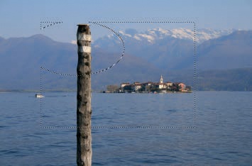
Although the selection is built the moment you release the mouse button, you can still move and change it. If the pointer is inside the selection, its icon is the crossed arrows that you see when the Move tool is active, as shown in Figure 13-14. You can move the selection itself (not the selected pixels) by clicking and dragging with the mouse, which is especially useful for making large changes to the position of the selection in the image. For minute adjustments, use the keyboard arrow keys, which move the selection by 1 pixel at a time. If you press and hold the ![]() key while using the arrow keys, the selection moves by 25 pixels at a time.
key while using the arrow keys, the selection moves by 25 pixels at a time.
If you place the mouse pointer near the corners or edges of the selection rectangle, its icon changes, as shown in Figure 13-15. This icon signals that the tool will now move the edges or the corners of the selection, allowing you to change the dimensions of the rectangle. You can do this with the mouse pointer or with the arrow keys. While you are pressing the ![]() key, the arrow keys will again work in increments of 25 pixels. Otherwise, they move the border of the selection by one pixel, allowing you to change the dimensions of the rectangle with a great deal of precision.
key, the arrow keys will again work in increments of 25 pixels. Otherwise, they move the border of the selection by one pixel, allowing you to change the dimensions of the rectangle with a great deal of precision.


When not within the selection rectangle, the mouse pointer icon looks exactly like it did before you built a selection. If the mode is set to the default, when you click and drag outside the current selection, that selection is discarded and a new selection is built.

To finalize the selection, click in the rectangle, press the ![]() key, or choose a different tool.
key, or choose a different tool.
The Rectangle Select tool has a number of options, as shown in Figure 13-16.
If checked, the ROUNDED CORNERS box displays options for the radius of the quarter circles that will replace the corners. See Figure 13-17 for an example.
If you check the EXPAND FROM CENTER box, the initial point where you click will be the center of the rectangular selection. Otherwise, it will be one corner of the rectangle. You can also activate this mode by pressing and holding the ![]() key after the initial click that begins the selection. Note that if you press
key after the initial click that begins the selection. Note that if you press ![]() before beginning the selection, it activates subtract mode, so the selected rectangle will be subtracted from the current selection. If the EXPAND FROM CENTER button is checked, pressing the
before beginning the selection, it activates subtract mode, so the selected rectangle will be subtracted from the current selection. If the EXPAND FROM CENTER button is checked, pressing the ![]() key (while in the process of building a selection) toggles that option.
key (while in the process of building a selection) toggles that option.
If the FIXED box in the tool options is checked, you can constrain the shape of the rectangle. The menu to the right contains the following choices:
ASPECT RATIO: When this is selected, the box below specifies the ratio between width and height and is initially 1:1, which corresponds to a square. You can change it to 1:2 or 4:3, for example. The small icons to the right of this box allow you to invert the ratio.
WIDTH: When this is selected, you can fix the width of the selection by typing a number in the box below. The drop-down menu to the right allows you to change the units or even use a percentage.
HEIGHT works in the same way.
SIZE: When this is selected, you can specify the exact dimensions of the rectangle in pixels. You can also enter a numeric expression like 257 × 7 or 85%.
Pressing and holding the ![]() key after you begin building the selection toggles the FIXED button.
key after you begin building the selection toggles the FIXED button.
The next four fields are used to adjust the position and size of the selection, either in pixels or in a variety of other units. The values shown change as you build or move the selection with the mouse pointer or the arrow keys. You can also set the size and position directly by typing in the boxes or clicking the arrows that appear to the right of each box.
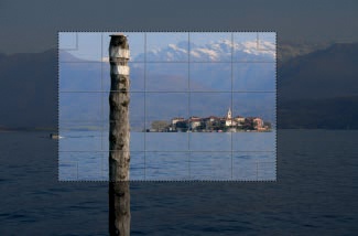
If you check the HIGHLIGHT box, the selection is highlighted, as shown in Figure 13-17. This highlight disappears when the selection is finalized.
The next option allows you to display guides while building the selection. Guides can help you to apply common composition rules when cropping photographs, for example.
NO GUIDES displays only the outer boundaries of the rectangle being built.
CENTER LINES places two perpendicular lines in the middle of the rectangle, as shown in Figure 13-18.
RULE OF THIRDS places two vertical and two horizontal lines in the rectangle, which divide it into nine identical parts. See Figure 13-19.
RULE OF FIFTHS places four vertical and four horizontal lines in the rectangle, dividing it into 25 identical parts. See Figure 13-20.
GOLDEN SECTIONS is similar to the RULE OF THIRDS, but the guides are aligned based on the golden ratio.
DIAGONAL LINES draws a line from each corner at 45°, which bisects the selection only in the case of a square.

Note that if you change the guides while building a selection, the new guides appear immediately.
The next two entries deal with the AUTO SHRINK mechanism, which is occasionally useful. To illustrate this mechanism, we drew a simple black shape on a white background, shown in Figure 13-21. We then made a rectangular selection roughly around the shape, as shown in Figure 13-22. When we click the AUTO SHRINK button, the selection shrinks to the smallest rectangle containing the object we drew, as shown in Figure 13-23.


Unfortunately, this option works only if the background is a solid color, so it’s not very useful on a photograph or a complex illustration.
When the SHRINK MERGED box is checked, all the visible layers are considered rather than simply the current one.

Access the Ellipse Select tool from the Toolbox (the second icon from the left in Figure 13-8), from the Image: Tools > Selection Tools menu, or by pressing ![]() . When this tool is active, the mouse pointer becomes a crosshair accompanied by a circular icon (Figure 13-24). It works in the same way as the Rectangle Select tool and has the same default options, except that the ANTIALIASING option is checked and enabled by default.
. When this tool is active, the mouse pointer becomes a crosshair accompanied by a circular icon (Figure 13-24). It works in the same way as the Rectangle Select tool and has the same default options, except that the ANTIALIASING option is checked and enabled by default.
Figure 13-25 shows the process of subtracting an elliptical selection from a rectangular selection. Figure 13-26 shows the result after finalizing the selection.

Access the Free Select tool from the Toolbox (the third icon from the left in Figure 13-8), from the Image: Tools > Selection Tools menu, or by pressing ![]() . When you select this tool, the mouse pointer appears as shown in Figure 13-27. The Free Select tool has only the options common to all selection tools. You can use this tool in two ways.
. When you select this tool, the mouse pointer appears as shown in Figure 13-27. The Free Select tool has only the options common to all selection tools. You can use this tool in two ways.
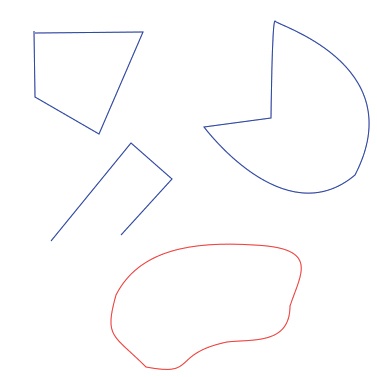
The first method is illustrated in Figure 13-28 and is best done with the stylus of a graphics tablet. To build a selection, click at the beginning of the outline of the intended selection and draw along it until you return to the initial point. When a white dot appears in place of the open circle, the outline is complete and will be closed once you release the mouse button. If you release the mouse button earlier, a hollow circle appears where the button was released. If you hover over the circle, it fills in, and the mouse pointer changes to the Move icon. If you move one of the endpoints of the selected curve, the orientation and size of the curve change, but the shape remains the same, as illustrated in Figure 13-29.
The Free Select tool can also be used to build a polygon by clicking on successive vertices, as illustrated in Figure 13-30. After each click, the point you just clicked is circled, and the pointer includes the Move icon, which indicates that you can move this last point. When the mouse pointer is close to the starting point, a closed circle appears on that point, and when you click, the path closes and the selection is finalized. As soon as this happens, the shape of the selection can’t be changed, at least not with the Free Select tool itself.


You can also combine the two Free Select methods. As you build a selection, you can add points by clicking, or clicking and dragging, from a point to draw a curved segment. Pressing ![]() finalizes the selection no matter how far the last point is from the beginning, linking the first and last points with a straight segment.
finalizes the selection no matter how far the last point is from the beginning, linking the first and last points with a straight segment.
This tool is handy for making a raw selection around a complex shape, which you can then refine using the Quick Mask, covered in depth in Chapter 14.


Access the Fuzzy Select tool from the Toolbox (the fourth icon from the left in Figure 13-8), from the Image: Tools > Selection Tools menu, or by pressing ![]() . When this tool is active, the mouse pointer is accompanied by the icon shown in Figure 13-31. The Fuzzy Select tool selects contiguous pixels with a similar color. Its options are shown in Figure 13-32.
. When this tool is active, the mouse pointer is accompanied by the icon shown in Figure 13-31. The Fuzzy Select tool selects contiguous pixels with a similar color. Its options are shown in Figure 13-32.
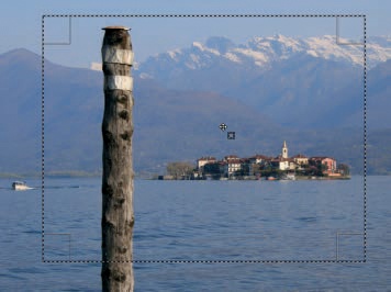
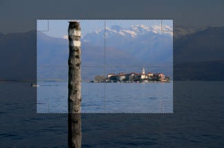
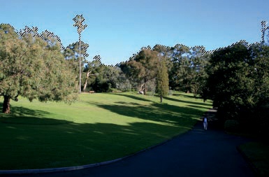
When we click and hold the mouse button somewhere in the sky of the image in Figure 13-33, an outline of the selected area appears. When we release the mouse, we get the selection shown in Figure 13-34, and the selection is indeed fuzzy. We’ve selected a portion of the sky using a very thick border, but our intention was to select the entire sky. You can extend the selected area in several ways:

Add other areas to the first one by pressing the
key while clicking in the nonselected areas. The best place to click in this case is within the fuzzy boundaries of the selection. -click the grass to select the entire meadow. You can also, of course, remove areas that don’t belong in the selection by pressing the key while clicking those areas.Increase the THRESHOLD in the tool options with the slider. The default value is 15.0 but can be set to any value from 0 to 255. The number you select is the maximum difference between the values of the initial pixel and the pixels that are selected.
Change the way the pixels are selected. The SELECT BY option brings up the menu shown in Figure 13-35. The default choice, COMPOSITE, uses all the components of an RGB pixel. But you can use only one of these components or one of the components of the HSV model. For example, in Figure 13-36, we used the Blue component, and one click was enough to select the whole sky—and only the sky.
While building a selection, keep the mouse button pressed and move the pointer along the diagonal from top left to bottom right. When you move the pointer up, the threshold decreases, and when you move it down, the threshold increases. The threshold change is reflected in the tool options dialog.

The Fuzzy Select tool has two more options that are handy if the image has transparency and multiple layers:
SELECT TRANSPARENT AREAS, when checked, allows you to include transparent areas as part of the selection.
In Figure 13-37, we added a new sky, which we took from another photograph. To do this, we selected the sky with the Fuzzy Select tool by selecting only the Blue component. We added an Alpha channel to the layer and cut the selection with
 . Finally, we inserted the other photograph as a new layer, using Image: Open as Layers (
 also works), and placed this new layer below the first one.
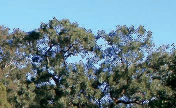
Now our image has multiple layers and a transparent area where the old sky was, so the status of the SELECT TRANSPARENT AREAS checkbox matters. Figure 13-38 shows an enlargement of part of this image. The cloudy sky is in the bottom layer, and the corresponding part of the top layer is transparent. But a little bit of the old blue sky was left between the trees. If the SELECT TRANSPARENT AREAS button is unchecked, you cannot select any pixel in the new sky. If it is checked, you can select both the old and the new sky and thereby apply transformations to all the blue sky areas in the image simultaneously.
SAMPLE MERGED allows you to make a selection that includes all visible parts of the image rather than just what’s present in the current layer. If the relevant area is completely transparent or opaque, checking this box has no effect. If the area is semitrans-parent, such that you can see elements from various layers, then the status of this option is important.


Access the Select by Color tool from the Toolbox (the third icon from the right in Figure 13-8), from the Image: Tools > Selection Tools menu, or by pressing ![]() . When this tool is selected, the mouse pointer appears as shown in Figure 13-39. Select by Color works in the same way as the Fuzzy Select tool (except the pixels selected need not be contiguous), and it has the same options. If we select in the Blue channel in the image shown in Figure 13-33, our selection now includes the blue areas beneath the trees, as shown in Figure 13-40.
. When this tool is selected, the mouse pointer appears as shown in Figure 13-39. Select by Color works in the same way as the Fuzzy Select tool (except the pixels selected need not be contiguous), and it has the same options. If we select in the Blue channel in the image shown in Figure 13-33, our selection now includes the blue areas beneath the trees, as shown in Figure 13-40.
Based on the example given, this tool may seem more useful than the Fuzzy Select tool. In reality, the best tool depends on the image and the goal. In this case, selecting the whole sky with the Select by Color tool was done with only one click. Unfortunately, however, the tool also selected blue areas in two other parts of the photograph. Figure 13-41 shows one of them, the shirt of a man walking on the path. To make this selection useful, you have to deselect these other blue areas before making adjustments to the sky.

Access the Scissors Select tool from the Toolbox (the second icon from the right in Figure 13-8), from the Image: Tools > Selection Tools menu, or by pressing ![]() (because this tool is sometimes called Intelligent scissors). When the tool is active, the mouse pointer appears as shown in Figure 13-42. This tool is useful for selecting complicated forms, provided their outline contrasts with the background. To use this tool, place control points along the outline of the object you intend to select. If these control points are well chosen, the line between two consecutive points will trace the outline of the object. Figure 13-43 shows a work in progress. The + sign next to the mouse pointer indicates that when you click, another point is added.
(because this tool is sometimes called Intelligent scissors). When the tool is active, the mouse pointer appears as shown in Figure 13-42. This tool is useful for selecting complicated forms, provided their outline contrasts with the background. To use this tool, place control points along the outline of the object you intend to select. If these control points are well chosen, the line between two consecutive points will trace the outline of the object. Figure 13-43 shows a work in progress. The + sign next to the mouse pointer indicates that when you click, another point is added.
If the points are placed too far from each other and the outline between them is not extremely clear, the tool may not trace the outline correctly. Unfortunately, this tool has no undo mechanism. But as long as the point you add is along the outline, you can salvage it by clicking the line to add another point and then dragging the point into place while pressing the mouse button. If you accidentally add a point that’s not along the object’s border, add another point farther along the border and then click and drag the errant point into place. If a partial selection is unsalvageable, change to another tool, return to the Scissors tool, and start from the beginning.


When the mouse pointer is close to the start point, it changes, as shown in Figure 13-44. After you click, the mouse pointer changes again, as shown in Figure 13-45. If you click inside the outline, it’s transformed into a selection, as shown in Figure 13-46.
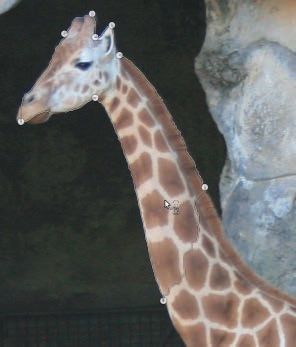

This figure illustrates the fact that the Scissors tool is not perfect. The lower jaw of the giraffe wasn’t selected because its outline didn’t contrast enough with the background. Errors such as this one are common. You will almost always need to refine a selection made with the Scissors tool by using another tool, such as Quick Mask, which is covered in Chapter 14.
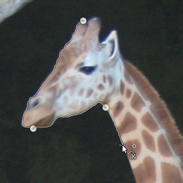
The Scissors tool has only one option in addition to the standard selection options. INTERACTIVE BOUNDARY, when checked, shows the outline between the previous control point and the one you’re about to place. This outline appears as soon as you click on the new point and changes if you drag the mouse pointer without releasing it. This allows you to see how far you can move the new control point before the outline detection stops working properly, which helps you to outline an object accurately using fewer control points. Figure 13-47 shows an example where we managed to select the lower jaw correctly.

Access the Foreground Select tool from the Toolbox (the rightmost icon in Figure 13-8) or the Image: Tools > Selection Tools menu. It is a somewhat complex tool, best explained by demonstration.

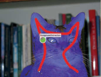
This tool is designed to select a complicated object that’s in the foreground of an image. When the tool is active, the pointer looks like the Free Select tool’s pointer. The sentence “Roughly outline the object to extract” appears in the mode line of the Image window. Begin by outlining the object in the same way that you would when using the Free Select tool, as shown in Figure 13-48. A more precise outline will lead to a better result, so take care with this step.
When the mouse button is released, the outline is finalized, and the selection appears in blue (by default), as shown in Figure 13-49. The message “Mark foreground by painting on the object to extract” is now displayed in the mode bar of the Image window, and the mouse pointer is that of the Paintbrush tool. Next, paint roughly over the cat in one continuous stroke to select it, as shown in Figure 13-50. When you release the mouse pointer after your first stroke, the message in the Image window will read “Add more strokes or press Enter to accept the selection.” Our result, at this stage, is shown in Figure 13-51. If you haven’t selected the cat completely, continue to paint over unselected areas. If you accidentally select some of the background, press the ![]() key to switch to deselect mode and paint over the areas that you accidentally selected. When you’re satisfied, press
key to switch to deselect mode and paint over the areas that you accidentally selected. When you’re satisfied, press ![]() to finalize the selection. Our final selection is shown in Figure 13-52.
to finalize the selection. Our final selection is shown in Figure 13-52.


Our final selection could still use a lot of work. The Foreground Select tool operates by selecting the colors that you paint over in the region that was outlined. If the colors of the object (the cat in this case) are similar to colors in the background, the selection won’t be very accurate, particularly if the outline includes a lot of the background.

The Foreground Select tool has many options, which are shown in Figure 13-53. When checked, CONTIGUOUS specifies that the selected area is a single, connected piece. Otherwise, the tool can select disjointed areas of similar color that fall within the outline drawn.
The following two radio buttons are equivalent to the ![]() key in that they allow you to toggle between selecting and deselecting colors with the paintbrush. The tool makes a new draft selection each time you release the mouse button. A slider lets you choose the size of the brush.
key in that they allow you to toggle between selecting and deselecting colors with the paintbrush. The tool makes a new draft selection each time you release the mouse button. A slider lets you choose the size of the brush.
Use the SMOOTHING slider to adjust the precision of the selection. The smaller the value, the higher the precision, but small holes in the selection may also result.
The PREVIEW COLOR menu allows you to choose among Blue, Green, or Red, and the best choice is the color that contrasts most sharply with the image.
Finally, the COLOR SENSITIVITY option allows you to use the LAB color model to increase or decrease the sensitivity of the tool to colors in the image by adjusting the three sliders. In this color model, L is the same as the Value channel in the HSV model, A is the difference between Red and Green, and B the difference between Blue and Yellow.