This chapter focuses on the construction of composite images using elements from several different photographs. The three main tools for this process are selections, overlaying, and blending modes.
As the preceding tutorial demonstrates, making selections is one of the most important, and trickiest, tasks involved in photo manipulation. So we’ll spend some time clarifying the functionality of the selection tools available in GIMP.
When you build a selection with the Rectangle Select tool, you get an area bounded by a simple geometric form. The simplicity makes it easy to tell whether pixels are within the selection. If you choose to feather the edges of the selection, however, the boundary is less clear: Some pixels are clearly out of the selection and some are deep within it, but what about those pixels on the feathered border?
The situation is even more complicated when you use the Fuzzy Select tool or the Select by Color tool. The selections that these tools build are usually not defined by clear and simple outlines. This shortcoming is obvious when you turn on Quick Mask, which displays the unselected pixels in red (by default). If the selection is feathered, you see that some pixels are completely red (unselected); others aren’t red at all (selected); and some pixels are, well, reddish. Figure 5-9 shows a feathered selection made with the Select by Color tool, whereas Figure 5-10 shows the same selection with the Quick Mask tool active. Both images are shown with a zoom factor of 800%.


As you may have guessed, those reddish pixels are partially selected. A selection and a mask are actually the same thing. They are both grayscale images that specify to what degree each pixel is selected. If the pixel value of the mask is 0 (i.e., black), the corresponding pixel in the image is not selected at all. If this value is 255 (i.e., white), the corresponding pixel is fully selected. A partially selected pixel has a value somewhere between 0 and 255.
Along the feathered edge of a selection, pixels are partially selected. All actions made to the selection affect these partially selected pixels to a lesser degree: Painting is semitransparent; burning is partial; cutting leaves some of the pixels in place; and so on. Partial selections are what make selections so useful in photo manipulation. They allow you to build composite pictures that don’t look like clumsy collages.
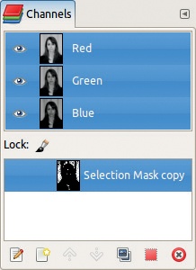
Because a selection and a mask are the same thing, and a mask is a grayscale image, you can manipulate it with the same tools that you would use on an image. You can paint on it with the painting tools demonstrated in Chapter 3. You can select and edit specific areas. And you can save it and use it later with Image: Select > Save to Channel. The mask appears as an additional channel in the Channels dialog, as shown in Figure 5-11. In this figure, the channel is selected (its line is emphasized), so if you paint on the image now, you’ll be painting on the mask. To paint on the image itself, switch to the Layers tab, select the layer you want to modify, and begin painting.
You can also use this property to change the mask in the same way we use the Quick Mask tool. To do this, open the Channels dialog and click the box to the left of the mask so the eye is visible. The mask now appears over the image (in gray by default). You can change the mask’s display color by selecting Channels: right-click > Edit Channel Attributes to open the dialog shown in Figure 5-12. You can change the channel’s name and its opacity, as well as the color of the mask. Click the large button on the right to open the Color chooser, where you can pick any color you want. But keep in mind that using a color that contrasts with the image is generally best.

When a selection (a mask) is saved in a channel, you can use it again later by simply clicking the red square button at the bottom of the Channels dialog. If you hover the pointer over the button, you’ll see that the standard key combinations allow you to activate different selection modes. You can save an unlimited number of selections as masks in the Channels dialog.
A mask used to determine the transparency of pixels in a layer is known as a layer mask. A layer mask is a part of a specific layer, and its pixels specify the transparency of the corresponding pixels in that layer. If a mask pixel is white, the corresponding layer pixel is opaque and thus visible in the image if not hidden by another pixel located in an upper layer. If a mask pixel is black, the corresponding layer pixel is transparent and thus invisible. Intermediate values for the mask pixels produce intermediate transparency levels for the layer pixels. Note, however, that the layer itself is unchanged.
You can add a layer mask by applying Add Layer Mask from the Image: Layer > Mask menu. Once added, you can access its options via the same menu. You can also add or manipulate a layer mask by right-clicking in the Layers dialog. When you add a mask to a layer, you can choose among several options: a completely white or completely black mask, the current selection, a specified channel, and others. Once you’ve built the mask, you can change it by painting on it, for example, with Quick Mask. You can change some of its properties, such as how it displays on the image. Finally, you can apply it to the layer, making its effect final.

We already demonstrated some of these options in previous chapters, and we come back to them later in this chapter.
Simply overlaying opaque images isn’t very interesting. Modifying the opacity of the top layer sometimes yields a satisfying result, but doing so doesn’t give us much control over it. Once you build a selection, however, you can create your own unique and imaginative images.
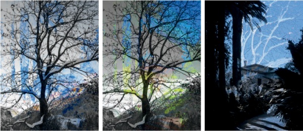
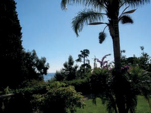
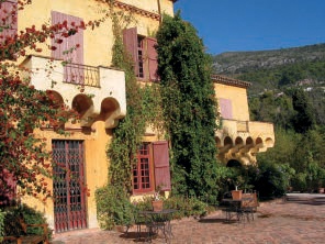
For example, take the photographs shown in Figure 5-13 and Figure 5-14. Open the first one, and add the second one as a layer (![]() ). Then, with the Fuzzy Select and Select by Color tools, select the sky in the top layer, which requires about a dozen clicks in several areas of the sky. Recall that pressing
). Then, with the Fuzzy Select and Select by Color tools, select the sky in the top layer, which requires about a dozen clicks in several areas of the sky. Recall that pressing ![]() allows you to add to the selection, whereas pressing
allows you to add to the selection, whereas pressing ![]() allows you to subtract from the selection. The completed selection is shown as a Quick Mask in Figure 5-15.
allows you to subtract from the selection. The completed selection is shown as a Quick Mask in Figure 5-15.


Our goal is to make the sky transparent so the building from the other photograph is visible behind the tropical vegetation. If we simply cut the selection, however, the sky is replaced by opaque white because the layer doesn’t contain any transparency (indicated by the boldface layer name) and so any cut pixels are replaced by the background color. To add transparency, add an Alpha channel to the top layer: Layers: right-click > Add Alpha Channel. Now if you cut the selection, you get Figure 5-16.
You can also use a selection to copy something from one photograph and paste it into another one. You did this earlier on a smaller scale when you created the composite portrait at the beginning of the chapter. Moving larger objects from one photograph to another presents its own challenges, as you’ll soon see.

As you saw previously, newly pasted objects are added to an image as a floating selection. They appear in the Layers dialog (which you should always keep visible in your workspace) and act somewhat like a layer located on the top of the stack. But as long as a floating selection exists, you can’t change anything else in the image. The other layers are inactivated, just as the unselected regions of an image are inactive as long as a selection exists.
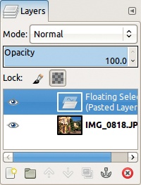
With a floating selection, you can do the following:
Create a new layer to contain the object you’ve just pasted.
Anchor the pasted content to whatever was active just before you created the floating selection. This layer might be the active layer (high-lighted in the Layers dialog) or the active layer mask (see the previous section), but not the active channel.
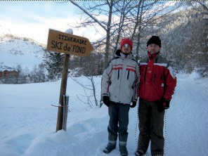
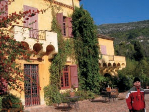
Let’s say you want to combine elements from the photographs shown in Figure 5-17 and Figure 5-18. You’ve decided to place an overdressed man in front of a sunny villa on the French Riviera. Select the man on the right, as shown in Figure 5-18. Make the selection with the Free Select tool and complete it by painting with Quick Mask. Don’t very careful when selecting his legs, however, because they won’t be visible.

Copy the selection from Figure 5-18 and paste it onto the image in Figure 5-17. The man appears in the center of the image, as shown in Figure 5-19, as a floating selection (see Figure 5-20).
Create a new layer for this floating selection and move the man to the bottom-right corner of the sunny scene. He’s darker than his surroundings, so select the Levels tool and add some light and contrast. Also apply Image: Layer > Transform > Flip Horizontally to flip him around. You can see the result in Figure 5-21.
GIMP has 21 blending modes, which you can select from the Layers dialog. The MODE option contains a drop-down menu with a list of blending modes that will act on the active layer. Each blending mode uses a different mathematical model to compute a new pixel value from the active layer and the layer below. Although we won’t go into any detail regarding the mathematics of blending modes, we will introduce some of the modes most useful for overlaying images.
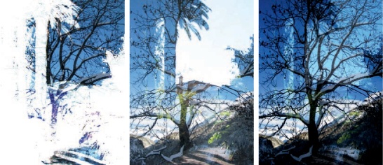
Begin with the photographs from Figure 5-22. Put them into the same image with the first one as the upper layer. The blending modes are arranged in a logical order, as explained in Chapter 12. In the following list, we briefly introduce these modes, in a different order, so we can run through them more quickly.
If the mode is set to Normal, the upper layer completely hides the lower one, except if its opacity is less than 100%. Figure 5-23 (left) shows an image with a top layer opacity of 50%. Each new pixel contains half of the upper pixel and half of the lower one.
Dissolve mode looks the same as Normal mode until you reduce the opacity of the top layer. As you decrease the opacity of the top layer, the layers are blended using dithering, and the resulting pixels are a random mixture of the upper and lower pixels. Opacity corresponds to the likelihood that the new pixel value will be taken from the upper layer. Figure 5-23 (middle) shows the effect of Dissolve mode with the top layer at 50% opacity.
In Multiply mode, the pixels’ values are multiplied and then normalized. The resulting pixels are darker than those of the initial layers. Figure 5-23 (right) shows the result of Multiply mode: black pixels whenever one of the pixels is black and light pixels only when both pixels are light.
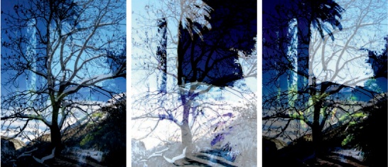
Divide mode divides and normalizes the pixel values. The result depends largely on the upper pixel. If the upper pixel is black, the result is almost white, as shown in Figure 5-24 (left).
The mathematics of Screen mode are more complicated. As Figure 5-24 (middle) shows, the dark areas in the top layer are more transparent than the light ones. If you want to learn more about Screen mode, flip ahead to Chapter 12.
Overlay mode combines Multiply and Screen modes and results in a washed-out upper layer. As Figure 5-24 (right) shows, the upper layer is no more than a ghost in the picture.
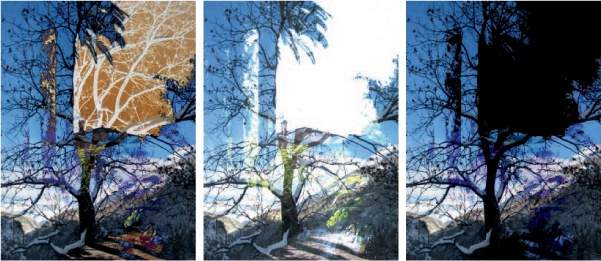
Dodge and Burn are the traditional techniques used in analog photo development to make areas in a picture lighter or darker. As you can see in Figure 5-25 (left and middle), these modes operate according to the same principles: The upper layer is used to dodge or burn the lower one, and the intensity of the action corresponds to the value of the upper layer.
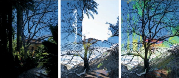
Hard light and Soft light are similar combinations of Multiply and Screen. As shown in Figure 5-25 (right), Hard light mode isn’t very useful in this example because the upper layer almost completely hides the lower one. As Figure 5-26 (left) shows, Soft light mode produces a more interesting result, although in this example, the result is very similar to Overlay mode (see Figure 5-24, right).
Grain extract and Grain merge are another pair of sibling modes. Grain extract is similar to Difference mode, whereas Grain merge is similar to Addition mode (which we explain next). These modes are suppose to mimic film grain, but sometimes the similarity isn’t apparent. Figure 5-26 (middle) illustrates how Grain extract uses the light areas from the upper layer to exaggerate the light areas in the lower one. Figure 5-26 (right) shows the more subtle effects of Grain merge, which uses the texture of the upper layer to change the lower layer.
Difference, Addition, and Subtract are also sibling modes. Difference mode, shown in Figure 5-27 (left), subtracts the lower pixel from the upper one and uses the absolute value of the result. The resulting image is difficult to predict. Addition mode, shown in Figure 5-27 (middle), adds pixel values, and values greater than 255 appear white. The resulting image is much lighter. Subtract mode, shown in Figure 5-27 (right), subtracts the pixel values, and values that would be negative appear black.
Darken only and Lighten only, shown in Figure 5-28 (left and middle), do what their names imply: The darkest or the lightest pixel is selected from the two layers.
The last four modes are related: The new pixel gets some combination of HSV components from the initial layers. In Hue mode (Figure 5-28, right), the upper layer colorizes the lower one. Saturation mode (Figure 5-29, left) takes the hue and value components from the lower layer. Color mode (Figure 5-29, middle) takes only the value from the lower layer. Value mode (Figure 5-29, right) is the exact opposite: It takes only the value from the upper layer.