
In this section, we cover tools for building animations that will be stored as a single image, with each layer acting as a frame. Some of these tools were used in Chapter 6, where we demonstrated simple animation techniques.
Suppose you want to move an object on a fixed background, as cartoon animators did 50 years ago. For example, how might you animate an old biplane landing in a field? You might try the method shown in 6.1 Tutorial: Animated Text, placing the plane in its successive positions in separate layers. But you have a problem: Each plane you position is added to the image instead of replacing the previous one, so the final animation is full of planes. And if you choose the replace mode in the layers, the background disappears as soon as the plane appears.
To make this animation work, you can do the following:
Duplicate the background for each plane layer.
Place the background layers below each plane layer.
Merge each plane layer with the underlying background layer.
Now the animation works, but making even a short animation by hand takes a long time. Wouldn’t it be great to have tools that automate parts of the animation-building process? With GIMP, we do.
The IWarp tool, accessed via Image: Filters > Distorts > IWarp, is demonstrated in Interactive Deformation, and its dialog is shown in Figure 6-32.
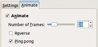
To use IWarp for animation, warp the image as you would warp a still photo, and then click the ANIMATE tab and choose to generate an animation. In Figure 18-2, we chose to create 20 frames between the first and last image, and we selected PING PONG, which repeats the animation in reverse. These settings result in 40 layers (20 forward and another 20 in reverse order), numbered from 0 to 39. Because the number of frames determines the animation’s smoothness, don’t reduce the number of frames unless the final file size is critical. If you plan to export the animation as a GIF file, you can optimize it to reduce file size later.
The Morph tool is part of GAP. It generates multilayer animations by progressively transforming one image into another. Use it to morph between images of people, as demonstrated in Chapter 6. You can also use it to morph one word into another, as we’ll demonstrate now.

In this example, the word “Windows” will be progressively morphed to the word “Linux!!” with just a few clicks.
First, build the logos using Image: File > Create > Logos > Glossy, with the default parameters, as shown in Figure 18-3. Enter Windows in the text field to create the first logo (Figure 18-4), and then enter Linux!! to create the second logo (Figure 18-5). Flatten both logos (Layers: right-click > Flatten Image) so they each contain only one layer. Copy the Linux layer to the Windows image as a new layer by dragging the layer thumbnail to the image.
Because the Linux layer is narrower than the Windows layer, you must increase its size to match via Image: Layer > Layer to Image Size. Also add an Alpha channel to both layers.
Now apply the Morph tool by selecting Image: Video > Morphing > Morph, which opens the dialog in Figure 18-6.


How you place the shape points determines how a point in the first image is morphed into a point in the second image. For a more complicated project, you should choose points carefully, but in this case, just click the SHAPE button, and the tool automatically creates and places points on the sides of both images.
The number of STEPS is the number of frames in the animation. Choose 20, click OK, and that’s it! The animation plays on a loop, but you can pause it between iterations by increasing the duration of the top layer. Optimize the animation and save it as a GIF.
Let’s explore this dialog section by section. In the top-left section, the SOURCE menu allows you to choose the source layer from the images open in GIMP. The X and Y boxes display the coordinates of the current shape point in the source layer. You can set these points by clicking the layer image, and you can adjust the coordinates using the vertical arrows at the right. Click FIT ZOOM to reset the zoom to show the entire source layer.
The top-right section is similar to the top-left section, except that it deals with the destination instead of the source layer. This section also includes POINT, which shows the current shape point. You can choose any shape point and then change or check its position with the X and Y boxes.

The bottom-left section of the dialog includes these options:
SHAPEPOINTS and SHAPE are used to set the number of shapepoints that are automatically placed and to place them. The more shape points you use, the more precise the morphing. But when you use more shape points, you also use more computing power. As a rule, place shape points where things change: You don’t need two points close to each other if no important variation occurs in the image between them.
The automatic shape points are placed along the outline of the source layer. Transparent pixels are not included in the outline.
If you
 -click the SHAPE button, the number of points specified is added to the existing number of points. Otherwise the specified points replace the existing ones.
RADIUS sets the size of the area influenced by every shape point.
STEPS sets the number of layers to be added or modified between the source layer (at the bottom) and the target layer (at the top). Any preexisting middle layers are modified.
The two color buttons to the right of the STEPS box set the colors of source and destination shape points.
LOCATE is useful for automatically locating features in the source and destination layers, but it can be time consuming because of the computations involved. It is triggered when you
 -click a shape point. The source shape point is automatically placed on the closest feature and the destination point on the feature that best matches the source. The first field in the dialog sets the radius in the source layer, the second field sets the radius of the area to be searched in the destination layer, and the last field is the edge-detection threshold for detecting a feature. You can play with these parameters, but their default values are already well chosen.
Finally, the bottom-right portion of the Morph tool dialog covers these settings:
EDIT MODE has five options. SET is the most versatile. It lets you add a new shape point by clicking in the source layer.
-click to create a new point that’s near an existing one. Right-click to delete an existing point. This mode also lets you drag existing points to a new position. MOVE mode is similar to SET, but clicking doesn’t create a new point.DELETE mode is used only to delete a point. The ZOOM mode allows you to zoom in on a specific point.
-clicking zooms out. SHOW mode should simply show the coordinates of the point you clicked, but as this book goes to press, this mode is unusable.INTENSITY is active if you select USE INTENSITY. When this box is checked, the shape point’s influence decreases geometrically with increasing distance from the point to the deformation radius. When the USE INTENSITY box is unchecked, the influence decreases linearly.
RENDER MODE can be set to Morph or Warp. MORPH is the normal mode. In this mode, the source layer transforms progressively into the destination layer by forward warps (warping the source layer into the destination layer), backward warps (warping the destination layer into the source layer), and cross fades. WARP makes the transition using only forward warps, but every time we’ve tried it, the results were strange and not very useful.
When checked (which it is by default), CREATE LAYERS creates the number of new layers indicated in the STEPS box. When unchecked, the existing layers are modified, but no new layers are created.
When checked, QUALITY uses a better transformation algorithm, but this algorithm is much more processor intensive and may crash the tool.
When checked, the LINES box displays small vectors that show how a specific shape point will be moved.
The RESET button removes all existing shape points.
The SWAP button exchanges the source and destination, but it does not move the layers in the image.
The SAVE and OPEN buttons do what you’d expect: SAVE saves all the shape point coordinates in a file, and OPEN loads previously saved coordinates. Open allows you to use the same shape points for different images or to save a partially completed project so you can return to it later, for example, to try different values for options.
This tool, accessed via Image: Filters > Filter all Layers is also part of GAP but operates on multilayer animations. The concept is simple:
Build a bunch of layers, for example, by duplicating a layer over and over.
Apply a transformation to all the layers using one of the many GIMP filters.
You can apply this filter using the same parameters for all layers, or you can change the parameter values progressively from layer to layer.
Figure 18-7 shows the Filter all Layers dialog. The menu on the left lists the many available filters, called plug-in-filter-name. The names are in alphabetical order. You can search for a specific filter using the buttons at the bottom right of the dialog:
SEARCH BY NAME compares the characters typed in the SEARCH box to the names of the available filters.
SEARCH BY BLURB searches in the filter’s description, located just above PARAMETERS in the top-right area of the dialog.
SEARCH BY MENU PATH searches in the menu path, located above the description.
In the first two cases, the string entered in the SEARCH box is treated as a regular expression. Searching using expressions is a complex concept, so we’ll provide just the basic explanation that you need to search efficiently. In short, a normal character, like a letter or a number, matches itself. A dot can stand in for any character, so c.l.r matches color and celar. An asterisk can match any number of occurrences of the preceding character, including none, so sear*ching matches seaching, searching, and searrrching. The dot and asterisk notations can also be combined, so color.*hance matches color-enhance, colorhance, and colorabcdhance.
When you select a filter in the left menu, its description appears on the right in the dialog. Most descriptions are written for GIMP developers rather than typical users, but you can still learn from them. The description gives you a general sense of what the filter does, and the parameter description gives you an idea of what you can change in the filter dialog.
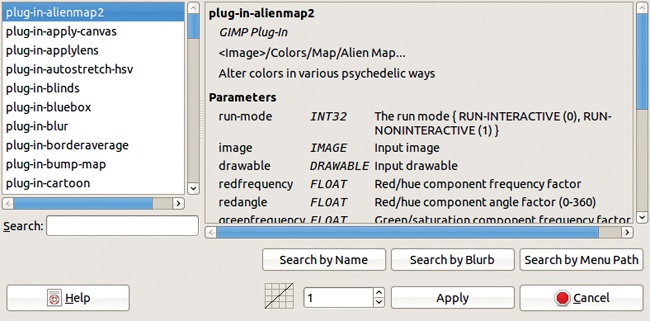
Once you’ve chosen a plug-in, the first two options at the bottom of the dialog may be active. They are inactive if the chosen plug-in does not have any parameters, as is the case for plug-in-blur. If these options are active, they let you choose acceleration characteristics:
0 means that the filter will be applied with the same parameter values for all layers. In this case, the box on the left is empty.
1 means that the parameters will vary, from the first value given to the last one, with constant speed. The box on the left displays an ascending diagonal line.
A negative value means the speed of variation will decrease (deceleration). The box on the left displays a convex curve.
A positive value (other than 1) means the speed of variation will increase (acceleration). The box on the left displays a concave curve.
You can set the acceleration value numerically or by using the small arrows on the right or by dragging the curve.
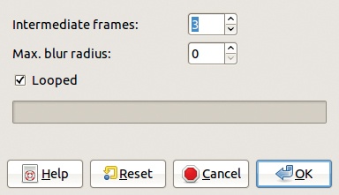
After making your selections, click APPLY. If the filter has parameters, its dialog opens, with a preview and the variable parameters displayed. If the acceleration is 0, this dialog appears only once because the parameters are the same for all the layers. If the acceleration is not 0, the filter dialog appears twice, first for the bottom layer and then for the top layer. Remember, animations are played from bottom to top. A tiny warning dialog precedes the second filter dialog. In this second filter dialog, you choose the final values of the filter parameters. A new dialog appears and asks for the name of a backup file to be used for building the intermediate layers. This file is about the same size as the final animation, but you don’t need to save it, so the name isn’t important and the file can be stored in a temporary folder.
Click CONTINUE, and the filter is applied to all the layers, with parameters interpolated between the first and last values according to the acceleration factor.
You’ll also see a button for skipping a frame. It displays the number of the frame to skip, and if you click it, the dialog appears again, asking for the filename. You can choose to continue or to skip the next frame also. You can’t skip the first frame, however. One way to use the skip feature is to set the initial parameters so the filter does nothing and then begin applying the filter after skipping several frames. Doing this is the same as setting the acceleration to a high positive number.

Filter all Layers has no undo capability, but you can use the normal undo (![]() ) over and over, or you can open the UNDO HISTORY dialog. Of course, if you have many layers, undoing one layer at a time will be tedious, so save the original image before filtering all the layers.
) over and over, or you can open the UNDO HISTORY dialog. Of course, if you have many layers, undoing one layer at a time will be tedious, so save the original image before filtering all the layers.