
There are eight entries in the Enhance menu. As in the Blur menu, the first entry lacks a dialog.
The Antialias filter can be used to add antialiasing to borders within an image.
Figure 17-21 (left) shows a line drawn with the Pencil tool, zoomed to 800%. Figure 17-21 (right) shows the same line after antialiasing. The filter operates instantly, without any dialog.
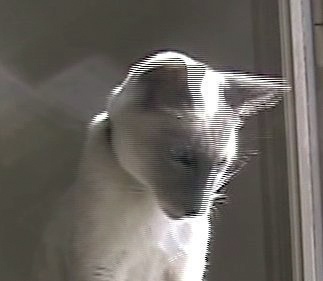
A video camera simulates motion by capturing a large set of images, usually 25 or 30 frames per second. More accurately, the video camera captures 50 or 60 half-frames per second. These half-frames, called fields, are composed of horizontal lines separated by a distance equal to their height. A frame is built by interlacing two fields from top to bottom. A line is taken from the first field, then a line is taken from the second field, and so on.
The two fields that are interlaced in a frame are not captured at precisely the same moment, which can result in a strange effect if the subject is moving quickly. This effect is shown in Figure 17-22.

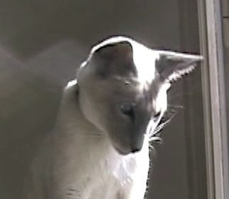
The Deinterlace filter removes half of the scan lines, either the odd ones or the even ones, and replaces each of them with an interpolation between the neighboring lines. Its dialog (see Figure 17-23) contains only a choice between the odd and even fields.
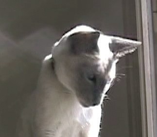
If you compare Figure 17-24 and Figure 17-25, you can clearly see the movement of the cat’s head.

Despeckle removes dots or scratches from images and can correct the speckled appearance of a scanned magazine page. However, it works automatically and can accidentally remove details from an image, so it should be used with care.
The photograph shown in Figure 17-26 is marred by tiny black dots due to its age. The Despeckle filter dialog (see Figure 17-27) contains a preview and the following parameters:
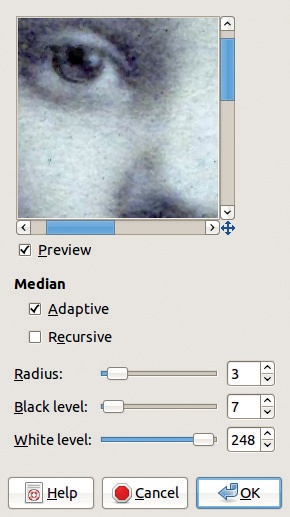
ADAPTIVE mode computes the radius based on the histogram. If unchecked, the radius is set manually using the corresponding slider (see RADIUS, below).
RECURSIVE mode causes the filter to act repeatedly on the image, which intensifies the effect.
RADIUS is relevant only in non-adaptive mode. It specifies the size of the area around each pixel, from 1, which corresponds to 3 × 3, to 20, which corresponds to 41 × 41. A larger radius blends surrounding colors and increases the filter’s processing time.
BLACK LEVEL sets the threshold value below which dark pixels are removed.
WHITE LEVEL sets the threshold value above which light pixels are removed.
Figure 17-28 shows the result of applying Despeckle in adaptive mode on Figure 17-26. Figure 17-29 and Figure 17-30 show non-adaptive mode results, with a radius of 2 for the first image and 7 for the second.

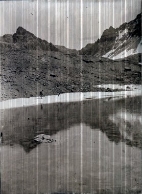
Destripe is used to remove vertical stripes generated by a poor-quality scanner. This filter creates a pattern of vertical stripes that cancel out the striping produced by the scanner. While this filter can be effective, selecting optimal settings can be challenging.
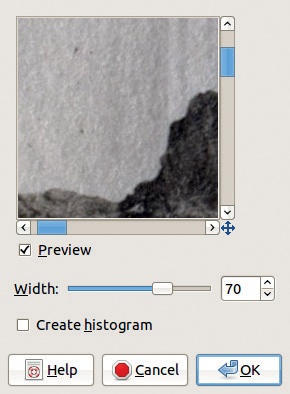
Figure 17-31 shows an initial, striped image, Figure 17-32 shows the filter dialog, and Figure 17-33 shows the effect of the filter. The only setting is WIDTH, which specifies the strength of the filter. High values are generally not advisable, since they often have no effect or, worse, they actually generate more stripes. Checking CREATE HISTOGRAM replaces the image with the pattern that would be used to destripe the image, which can be used to create interesting textures.

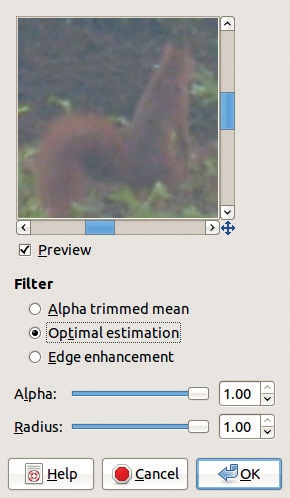
NL (Non Linear) Filter does a variety of things. It requires a layer without an Alpha channel, and it uses a hexagonal block of pixels surrounding the target pixel instead of the square blocks used by most other filters. Depending on the mode setting, NL Filter can apply three transformations (see Figure 17-34):
ALPHA TRIMMED MEAN smooths the image when the ALPHA value is low, and it removes noise when ALPHA is at its maximum. RADIUS specifies the effect’s intensity.
OPTIMAL ESTIMATION uses an adaptive method to smooth the image, which is good for removing noise due to dithering in color images. ALPHA specifies the noise threshold, above which the filter has no effect, and RADIUS specifies the effect’s intensity.
EDGE ENHANCEMENT sharpens the image, and ALPHA sets the intensity of the effect, while RADIUS controls the width of the edges.
Red Eye Removal is an automated tool for correcting the effect of flash photography on a person’s pupils. Depending on the image, this filter can work well or quite poorly.
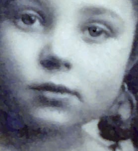
First, try this filter on the photograph shown in Figure 2-77. The red color in the girl’s eyes isn’t very saturated or bright. When the filter is selected, the dialog shown in Figure 17-35 appears. The preview shows that if the default parameters are used, the lips and the left cheek will be discolored. The dialog informs us that “Manually selecting the eyes may improve the results.”


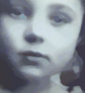
Select the eyes by drawing a rough outline around them with the Free Select Tool, and choose the filter again. This time, after an adjustment with the THRESHOLD slider, the result looks good. The dialog is shown in Figure 17-36, and the result is shown in Figure 17-37.
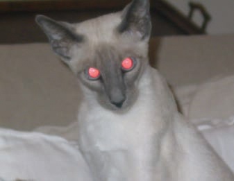
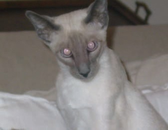
In the second example (see Figure 17-38), the red color is very bright but not very saturated. In the HSV model, the S value is 48 and the V value is 100. The filter doesn’t work very well under these conditions, as shown in Figure 17-39. In the final image, the eyes look dull, and the bridge of the nose has a red cast.
For more tips on removing red eye, see More Correction Methods for Red Eye.
Sharpen is a simplified version of Unsharp Mask, which is the next filter in the menu. Sharpen works well for simple tasks, like enhancing a photograph that’s blurry because of the interpolation that occurs in a digital camera or a scanner or due to an image’s being scaled up or down. Edges are almost always slightly blurred in a digital photograph, and the simple Sharpen filter in GIMP works much better than the builtin correction features of current digital cameras. The filter’s dialog has only one parameter: SHARPNESS.

Figure 17-40 is a good example of a photograph that would benefit from sharpening. Color and size adjustments led to interpolation, which left the image very blurry. Figure 17-41 shows the result of using the Sharpen filter with a sharpness of 77.
Despite its paradoxical name, the Unsharp Mask filter is an excellent sharpening tool, offering much more control than the Sharpen filter.
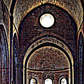
The parameters allow you to adjust the amount of sharpening. Note that color distortions may occur if the amount is really high. A dramatic example is shown in Figure 17-42. To sharpen a picture dramatically without color distortion, first decompose the initial image to HSV layers. Select Image: Colors > Components > Decompose, and choose the HSV model and DECOMPOSE TO LAYERS.
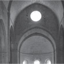
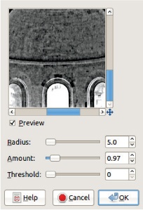
Hide the Hue and Saturation layers, and from the Value layer (Figure 17-43), select the Unsharp Mask filter and set the parameters as shown in Figure 17-44.
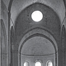
After sharpening the Value layer, as shown in Figure 17-45, select Image: Colors > Components > Recompose. The result is shown in Figure 17-46. By carefully adjusting the parameters, it’s possible to get a much better result than with the Sharpen filter. Note that it’s always best to sharpen an image after it’s been scaled to its final size and resolution.
The three parameters of Unsharp Mask are as follows:
RADIUS specifies the width of the mask and, as a result, the visibility of the sharpening effect. The optimal value depends on the resolution of the image and the size of the details within it.
AMOUNT specifies how much edge contrast will be created. A large value exaggerates the edge by adding a rim to it (see Figure 17-42).
THRESHOLD specifies the minimum difference between pixel values that indicates an edge. In effect, it separates signal from noise. A high value prevents false detection of edges but also reduces the effect of the filter.