The blending modes apply an additional color plane to an image, either as a layer or as a design created with the painting tools. Figure 12-6 shows 21 of the 23 blending modes available for painting tools. In layers, the Behind and Color erase modes are not available.
The blending modes are arranged in the menu according to their effect. The first four modes (Normal, Dissolve, Behind, and Color erase, or just the first two for layers) leave the pixels intact and change only which pixels are displayed. The next four modes (Lighten only, Screen, Dodge, and Addition) lighten the image and are arranged by impact, from least to greatest. The next three modes (Darken only, Multiply, and Burn) darken the image, and they are also arranged by impact, from least to greatest. The next three modes (Overlay, Soft light, and Hard light) alter the image’s luminosity. The next five modes (Difference, Subtract, Grain extract, Grain merge, and Divide) distort the image’s hues rather than just its saturation and value. The last four modes (Hue, Saturation, Color, and Value) use the HSV model components as the basis for blending the layers.


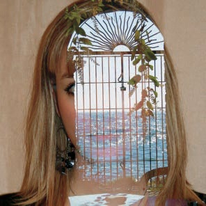
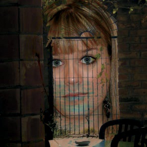
To demonstrate the blending modes, we’ll build an image with two layers. Figure 12-7 is the top layer, and Figure 12-8 is the bottom layer. We’ll use specific examples for the two modes that exist only with the painting tools.

We also need a notation for explaining the mathematics underlying the blending modes. Recall that a pixel is made of three values—the channels R, G, and B—and so can be thought of as a vector. We’ll use U to refer to the vector of a pixel in the upper layer, L to refer to the vector of a pixel in the lower layer, and R to refer to the vector of the resulting pixel.
The four modes in this category have an important property in common: They all assign a value to R by taking the exact values either from U or from L.
In Normal mode, the upper pixel is always chosen (i.e., R = U). But if U isn’t fully opaque, then the value of R is a combination of U and L. If the opacity of U is set to percentage x, then
Figure 12-9 shows the result when the top layer opacity is 50%. Opacity works in the same way for all of the blending modes.
In Dissolve mode, the choice between the upper and lower pixel is random but proportional to the opacity. Given a function f(r) that yields a random result between 0 and 1, the formula is R = [if 100 × f(r) < x] then U, else L. Figure 12-10 shows this result with 50% opacity, and Figure 12-11 magnifies a portion of this image.

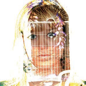
To demonstrate Behind mode, we’ll use Figure 12-12. We first removed the portrait’s background, replacing it with transparency. An underlying white layer is visible beneath the portrait layer. If we paint on this image in Behind mode, only the transparent pixels are affected, as shown in Figure 12-13. If semitransparency had been used rather than full transparency, we would see a combination of the green and semi-transparent background color.
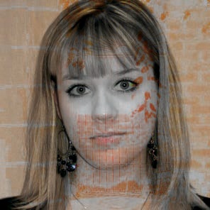
Color erase mode removes the color that you’re painting with from the image and replaces it with partial transparency. In Figure 12-14, we used a large round brush and selected the hue of the face as the foreground color by ![]() -clicking the girl’s left cheek. The white background layer is visible through the semitransparency.
-clicking the girl’s left cheek. The white background layer is visible through the semitransparency.

When you use lightening modes, the image will be lighter than in Normal mode.
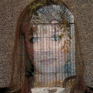
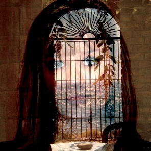
In Lighten only mode, the resulting pixel is the same as the lighter of the two pixels being blended. In Figure 12-15, the brightly lit seascape was taken from the upper layer, and the rest was taken from the lower layer. The formula is simply R = max(U, L).
Screen mode yields an even lighter result via a more complicated formula:
The upper and lower pixels are inverted, which is done by subtracting their value from 255 (in 8-bit depth). The results are multiplied, and then the product is normalized to subrange [0 to 255] by dividing it by 255 and inverting it again. As you see in Figure 12-16, the dark areas of the upper layer disappear, the light areas look washed out, and the image seems to be more transparent.

Dodge mode exaggerates the lighting. The formula for this mode is:
The lower pixel value is multiplied by 256 and then divided by the inverse value of the upper pixel. To prevent division by 0, 1 is added to the divisor. Figure 12-17 shows the result. This mode works best when used with a painting tool to simulate the dodging process used in the darkroom to decrease exposure in specific areas. This mode can be used to bring out details in the darkest areas of an image.


Addition mode exaggerates the lighting even further without any color inversion. Some areas may become completely white, as shown in Figure 12-18. To achieve this result, the pixel values are added, and then the result is truncated to 255 because greater values can’t be represented in the RGB cube. The formula is R = min(U + L, 255).
With these modes, the resulting image is darker than the original.

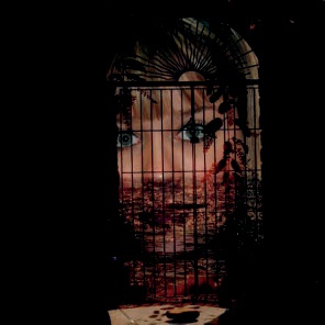
Darken only mode is the opposite of Lighten only mode: The resulting pixel is the darker of the two pixels being blended. As shown in Figure 12-19, the resulting image contains content from the upper layer where it’s darker and the lower layer elsewhere. The formula is R = min(U,L).
In Multiply mode, the pixel values are multiplied, and the result is normalized by dividing by 255: R = (U × L)/255. As Figure 12-20 shows, the result is much darker than the two layers.
Burn mode simulates a darkroom process, similar to Dodge mode, and also works best with painting tools. This mode decreases the exposure of the image and can lead to a loss of detail in dark areas. The formula for this mode is:

The lower pixel value is inverted and divided by the upper pixel value. That number is then normalized by multiplying by 256, and the result is inverted. Again, 1 is added to the divisor to prevent division by 0. In Figure 12-21, the only parts that are not completely burned out are those that were light in both layers.
The three modes in this section are so similar that the first two currently have identical effects.

These modes deal with the luminosity of the image rather than its colors.
Overlay mode combines Multiply and Screen modes, and it darkens the image a little less than Multiply. Its complicated equation is theoretically this:
But in GIMP 2.8, this mode actually uses the equation for Soft light mode. This bug has intentionally been left because correcting it would result in unexpected changes appearing in existing images that use Overlay mode. Developers are currently working on a strategy to correct the bug without altering existing images.
The equation for Soft light mode incorporates the result of the Screen mode calculation, here called RS:
As Figure 12-22 shows, the resulting image is darker than the original image, having dim colors and softened edges.
Hard light mode uses the most complicated equation of all the modes. It handles darker colors differently than brighter colors. Hard light is yet another combination of Multiply and Screen, and it results in brighter colors and sharper edges (i.e., the exact opposite of Soft light). The upper layer is treated differently than the lower layer, unlike most of the modes already considered. Figure 12-23 and Figure 12-24 show two examples, with the layer order reversed in the second one. The equation is as follows:
If U > 128:
If U ≤ 128: R = (2 × U × L)/256


These modes distort colors in various ways.
In Difference mode, the resulting pixel is the absolute value of the difference between the upper and lower pixels: R = |U – L|. For example, if U = 50 and L = 200, then R will be the absolute value of –150, which is 150. When this occurs, the colors appear to be inverted, as shown in Figure 12-25.


Subtract mode is based on the same idea as Difference mode, but it doesn’t take the absolute value after subtraction. This means the order of the layers affects the result, as illustrated by Figure 12-26 and Figure 12-27. Subtract mode deals with negative values by setting them to 0, according to the following formula: R = max(U – L, 0). Any 0 values correspond to black areas.
According to its name, the Grain extract mode should extract the film grain from a layer, but whether it does this is debatable. Some people think it gives images an embossed appearance. Figure 12-28 and Figure 12-29 show the effect of Grain extract on our example images. The official formula is R = L – U + 128, but negative values or values greater than 255 are truncated. Negative values are replaced with 0, and values greater than 255 are replaced with 255.


Whereas Grain extract mode extracts the grain from the layer, Grain merge mode merges the grain layer into the current layer. This mode is symmetric, so the order of the layers doesn’t matter. Our result is shown in Figure 12-30. The formula for this mode is R = U + L – 128, and again, values that are negative or greater than 255 are truncated.
Divide mode is yet another nonsymmetrical mode, wherein the value of the lower pixel is divided by that of the upper pixel (plus 1). The result is multiplied by 256 to normalize the value. The result, shown in Figure 12-31, is lighter than the original and completely white in some places. The equation is

The last four modes operate in the HSV space. They work by replacing one component (hue, saturation, or value) in the upper layer with the corresponding component from the lower layer.
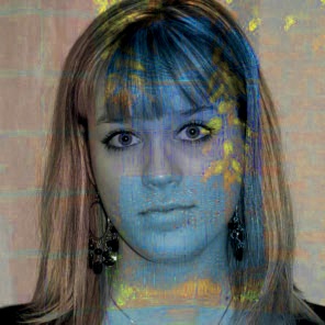
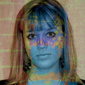
In Hue mode, the resulting pixel has the hue of the upper pixel and the saturation and value of the lower pixel. But if the saturation of the upper pixel is 0, the hue is also taken from the lower pixel. This explains why in Figure 12-32, the pixels corresponding to the black areas in the upper layer are completely replaced with the pixels from the lower layer.
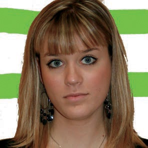
In Saturation mode, the saturation is taken only from the upper layer. Because the saturation of the top layer was low throughout most of the image, the result, shown in Figure 12-33, is almost completely unsaturated.
In Color mode, the hue and saturation are taken from the upper layer, whereas the value is taken from the lower layer. As shown in Figure 12-34, the effect is that the lower layer is painted with the upper layer’s colors.
In Value mode, the value is taken from the upper layer, and the saturation and hue are taken from the lower layer. As shown in Figure 12-35, the result of this mode is the reverse of Color mode: The upper layer is painted with the colors of the lower layer.