The Distorts menu includes 18 loosely related filters. All 18 filters have a dialog, but the Engrave filter requires an Alpha channel and will be grayed out if none exists. We omit three filters because they are seldom useful: Blinds, Erase Every Other Row, and Video.

Apply Lens simulates a distorted view of the image through a spherical lens, as shown in Figure 17-47.
The dialog, shown in Figure 17-48, contains settings for the refraction index of the lens [1 to 100] and the handling of the image surroundings, which can be retained, made transparent (an Alpha channel is required), or filled with the background color.
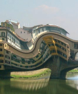
Curve Bend deforms the contents of an image based on a curve that you can manipulate in the filter dialog.
When the filter is selected (in this case to work on the image in Figure 17-49), it brings up the dialog shown in Figure 17-50. The AUTOMATIC PREVIEW button is unchecked by default, because it’s processor intensive, and generally it’s best to use PREVIEW ONCE instead. On the right are the curves. You can choose to deform the UPPER or LOWER curve. If the Curve Type is SMOOTH, add points to the curve and move the points to deform it further. If the Curve Type is FREE, build the curve by drawing in the grid with the mouse.
You can COPY the upper curve to the lower one, and vice versa, or MIRROR them or SWAP them. You can also RESET the current curve. The settings of the curves can be saved to a file and loaded later.

The SMOOTHING and ANTIALIASING buttons on the left should usually be left checked. When WORK ON COPY is checked, the transformation is done to a new layer, and the original layer isn’t changed. Finally, you can use the ROTATE field to rotate the curves on the layer. If the rotation angle is 90°, the curves will align vertically, with the upper curve on the left side.
Figure 17-51 shows our result. The current background color fills empty areas in the image.

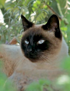
Emboss is available only for RGB images. It uses the values of the image’s pixels to create relief. Bright areas are raised, and dark ones lowered.
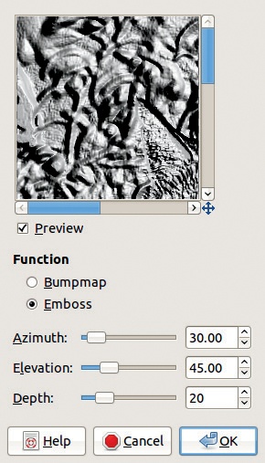
The dialog, shown in Figure 17-52, has three parameters:
AZIMUTH is the direction of the light source. When this is set to 0°, the light appears to be coming from the right. When this is set to 90°, the light appears to come from above.
ELEVATION is the angle of the light source above the horizon.
DEPTH specifies the intensity of the relief. With a very low value, the embossed relief is almost flat. With a high value, the image is dark and shadowy.
The result, shown in Figure 17-53, is a grayscale image in RGB mode. If BUMPMAP is checked, the result is in color, and the relief is smoother (see Figure 17-54).
Engrave requires an Alpha channel. It simulates the engraving found in old books, in which horizontal stripes of variable width give an impression of relief.
In the Engrave dialog, HEIGHT is the width of the lines, and small values correspond to thinner lines. LIMIT LINE WIDTH, if checked, ensures that the parallel lines don’t touch.

The result of this filter is a black and white image in RGB mode (Figure 17-55).
Because it can be used in animation, this filter is covered in detail in Chapter 18. It can be used to create a silly caricature or to make subtle changes to a photograph.


We demonstrate on a picture of one of the authors of this book, who will surely not sue us for what we’re doing to him (see Figure 17-56). With a deform radius of 20, we moved the nose down, enlarged both eyes, swirled the mouth in both directions, and shrank the chin. With a radius of 72, we moved the hair down on the forehead. The disturbing result appears in Figure 17-57.
Lens Distortion simulates the various distortions that can occur due to camera lens imperfections. Since a distortion in the reverse direction can cancel an existing one, this filter may also be used to correct real camera distortions.


Figure 17-58 shows the filter dialog when applied to the photograph shown in Figure 17-59. The preview has two zoom buttons, and there are six setting sliders, which all have a range of [–100 to +100]:
MAIN is the strength of the spherical distortion. If it’s positive, the effect is convex, and if it’s negative, the effect is concave.
EDGE works like MAIN, above, but it acts on the edges of the image.
ZOOM enlarges or reduces the image.
BRIGHTEN sets the so-called vignetting effect: if positive, the edges of the image are darker, and if negative, they’re brighter.
XSHIFT specifies a horizontal image shift caused by poor lens alignment.
YSHIFT does the same but vertically.


If the values of MAIN and EDGE are both low, the effect of changing the other sliders may not be perceptible.
The result is shown in Figure 17-60. To find the proper settings to correct the results of a digital camera, you could take a picture of a large rectangular sheet with straight lines on it. Since the pattern is simple and bold, you can adjust the parameters until you have corrected any distortion and then note the parameter values.

Mosaic simulates a mosaic by breaking the image up into small tiles. Its dialog, shown in Figure 17-61, has many settings:
TILING PRIMITIVES allows you to pick the shape of the tiles.
TILE SIZE [5 to 100] is the size of the largest side of the tiles.
TILE HEIGHT [1 to 50] controls the amount of relief. If this value is large relative to tile size, the tiles become spherical.
TILE SPACING [1 to 50] is the width of the black channels between tiles.
TILE NEATNESS ranges from 0 (totally random tile shapes) to 1 (totally regular tile shapes).
LIGHT DIRECTION determines how the tiles are lit. It is generally best left at the default value of 135° (lit from the upper left).
COLOR VARIATION ranges from 0 (homogeneous blocks of tiles) to 1 (strong color variations between neighboring tiles).
ANTIALIASING smooths the tile contours.
COLOR AVERAGING makes each tile a single color, which is the average of the pixels it contains.
ALLOW TILE SPLITTING allows very small tiles such that the tile pattern follows the object borders in the image.
PITTED SURFACES gives the tiles a rough surface texture.
FG/BGLIGHTING uses the foreground color for light areas and the background color for shadowy areas.
The result is shown in Figure 17-62.

Newsprint simulates the dithering used to convert an image for offset printing, for a newspaper for example.
The dialog is shown in Figure 17-63. (We have omitted the preview to save space.) The parameters are divided into three groups:
RESOLUTION specifies the size of the colored spots that will make up the image.
SCREEN controls the dithering parameters.
SEPARATE TO has three radio buttons that determine the color space for decomposition. In RGB, there is no conversion. In CMYK, the image is internally converted, then dithered, and then converted back to RGB. In INTENSITY, the image is internally converted to grayscale, and the final result is used as an Alpha channel for the image.
BLACK PULLOUT determines the percentage of black used when converting RGB to CMYK.
LOCK CHANNELS copies the settings below it from one channel to the others.
FACTORY DEFAULTS resets the channel parameters to their default values.
For each channel, the ANGLE of the cell grid and the SPOT FUNCTION can be set.
ANTIALIASING is useless when printing but useful if this filter is being used for special effects.
Figure 17-64 displays the result.


Pagecurl simulates the curling of paper. The dialog (Figure 17-65) has the following parameters:
CURL LOCATION: The four radio buttons allow you to choose the corner that will curl, and an icon in the middle illustrates the current selection.
CURL ORIENTATION: The fold can be horizontal or vertical, and the icon in the dialog also reflects this selection.
SHADE UNDER CURL: Checking this box adds a shadow to the image, beneath the curl.
The colors used for the underside of the page are the current foreground and background colors, the current gradient, or the current gradient reversed.
The fold is created as a new layer, and its opacity can be set in the dialog of the filter, as well as in the Layers dialog.
Figure 17-66 shows the result of the Pagecurl filter.

Polar Coordinates transforms a rectangular image into a circular one by wrapping and stretching the image.
In the dialog of Polar Coordinates, CIRCLE DEPTH IN PERCENT determines how circular the result will be. At 100%, the result is a perfect circle, and if it is 0%, it is a square. Intermediate values yield a square with rounded sides. OFFSET ANGLE rotates the image by the specified angle.


The three checkboxes do the following:
MAP BACKWARDS maps the pixels from right to left, instead of from left to right.
MAP FROM TOP maps the top of the image to the center of the circle. By default, the bottom is mapped to the center.
TO POLAR maps the image to a circle, cuts along the top and vertical radius, and then extends the image to create a rectangle.
The result of Polar Coordinates is shown in Figure 17-67. The background color is white, and the MAP FROM TOP button is checked.
Using the photo shown in Figure 17-68, and unchecking the MAP FROM TOP button, we get in Figure 17-69 a new planet in the black sky provided by the background color.


Ripple simulates the reflection of the image on a rippled water surface.
Its dialog, shown in Figure 17-70, offers the following parameter settings:
ANTIALIASING softens the borders in the image and is best left checked.
RETAIN TILABILITY should be checked if you’re building a tilable pattern.
ORIENTATION allows you to select horizontal or vertical ripples.
EDGES specifies what should be done with empty spaces along the image’s edges:
WAVE TYPE may be SINE for smooth ripples or SAWTOOTH for spiky ones.
PERIOD [1 to 200] specifies the distance between two consecutive ripples.
AMPLITUDE [0 to 200] specifies the height of the ripples.
PHASE SHIFT [0 to 360] changes the distance between the beginning of the first ripple and the edge of the image.
Figure 17-71 shows the result of Ripple.

Shift displaces all pixels in the image, vertically or horizontally, by a random amount within set limits.


The dialog contains only a few settings:
Direction of the shift, either vertical or horizontal
Maximum amount of the shift, in pixels or alternative units
Figure 17-72 shows the result of Shift on our garden photo.
Value Propagate spreads pixels at the color borders of the image.
We demonstrate on the image shown in Figure 17-73. Since there are many adjustable parameters, we show a couple of interesting alternative results.


The many parameters are shown in Figure 17-74. First, take a look at the PROPAGATE section. At the bottom, there are four check-boxes for the four directions; most of the time it’s best to check all four. The three sliders specify the intensity of the transformation. A pixel will not be propagated if its value difference from its neighbor is lower than the LOWER THRESHOLD or greater than the UPPER THRESHOLD. The amount of propagation is specified by the PROPAGATING RATE.


The mode determines which pixels will propagate. The available modes are these:
MORE WHITE propagates the bright pixels to the dark ones. Figure 17-75 shows the result after three applications.
MORE BLACK propagates the dark pixels to the bright ones. Figure 17-76 shows the result after three applications.
MIDDLE VALUE TO PEAKS adds a thin border to the edges, computing its color as the average of the neighboring pixels. Figure 17-77 shows an enlargement of its effect.
FOREGROUND TO PEAKS fills the propagated pixels with the foreground color. In Figure 17-78, the foreground color was bright green.
ONLY FOREGROUND/BACKGROUND propagates only the pixels that are the foreground or background color.
MORE OPAQUE/TRANSPARENT propagates the pixels that are opaque or transparent.


If the current layer has an Alpha channel, two more checkboxes appear in the dialog. If PROPAGATING ALPHA CHANNEL is unchecked, the propagated pixels use the Alpha of neighboring pixels instead of their own Alpha. If PROPAGATING VALUE CHANNEL is unchecked, the filter operates only on the Alpha channel.
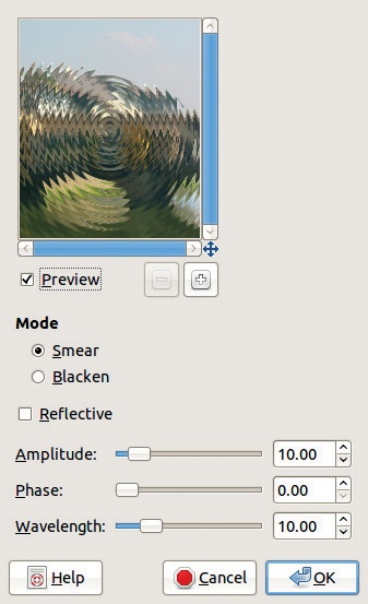

The Waves filter simulates the concentric waves that occur when a stone is dropped into water.
In the dialog, shown in Figure 17-79, the parameters are very similar to those of the Ripple filter. The only new parameter is REFLECTIVE: If this is checked, the waves bounce off the image edges and interfere with one another.
Figure 17-80 shows the result of Waves.

Whirl and Pinch applies two different distortions to the image. Whirl swirls the image in a pattern similar to water going down the drain, and Pinch distorts the image as if it were a sheet of rubber.
The dialog shown in Figure 17-81 contains only three sliders:
WHIRL ANGLE [–720° to +720°] is the angle of rotation of the whirl distortion.
PINCH AMOUNT [–1 to +1] is the intensity and direction of the pinch. A negative value expands from the center, while a positive value squeezes the image inward.
RADIUS specifies how much of the image is distorted, from 0 (none) to 2 (the entire image).
See Figure 17-82 for the result.
The Wind filter adds thin horizontal lines to the image in order to create the illusion of strong wind.
The dialog shown in Figure 17-83 offers the following parameters:
STYLE is WIND (very thin lines) or BLAST (thicker lines).
DIRECTION is from LEFT or RIGHT.
EDGE AFFECTED is the leading one, the trailing one, or both.
THRESHOLD [0 to 50] is used to detect borders.
STRENGTH [1 to 100] is the strength of the effect.
Figure 17-84 shows the result.