
This is yet another menu with a series of disjointed entries. The first five are related to light, the next three to shadows, and the last two are glass effects. We omit the Xach-Effect filter, which we consider not very useful.
Gradient Flare simulates the effect that a strong light source can have on a camera lens. The flare is made up of three parts: the Glow, which is the central circle of light; the Rays, which are the streaks of light that extend from the Glow; and the Second Flares, which are the smaller circles of light that sometimes appear in a line, extending out from the Glow.
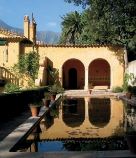
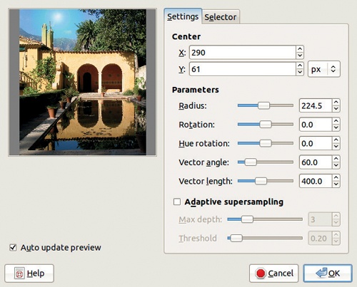
We demonstrate on the image shown in Figure 17-85. The dialog of Gradient Flare has two tabs, as shown in Figure 17-86. From the Settings tab, you can set the position of the main flare by typing in coordinates, or you can click the preview to specify the position. The other parameters are these:


RADIUS [0 to 248] specifies the radius of the glare. The slider stops at a rather low value, but you can type a much larger value into the field on the right.
ROTATION [–180 to +180] changes the rotation of the Glow.
VECTOR ANGLE [0 to 359] changes the orientation of the Second Flares.
VECTOR LENGTH [1 to 1000] changes the length of the Second Flares.
ADAPTIVE SUPERSAMPLING contains parameters for antialiasing.
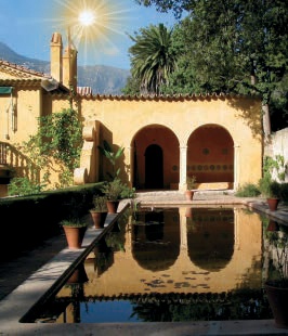
The Selector tab of the Gradient Flare filter, shown in Figure 17-87, offers seven predefined flares, which you can select by clicking them. See Figure 17-88 for the result of choosing DISTANT_SUN.

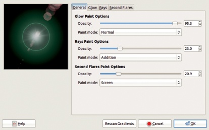
In the Selector tab (Figure 17-87), four buttons at the bottom allow you to copy an existing flare, edit it, or delete it, or create a new one. The EDIT button brings up the dialog shown in Figure 17-89, with four tabs. The General tab lets you set OPACITY and PAINT MODE. PAINT MODE contains four options: NORMAL, ADDITION, OVERLAY, and SCREEN.
In the Glow tab of the Gradient Flare editor (Figure 17-90), you can choose gradients for the three elements that define the Glow component. Any of the predefined gradients called Flare ... will generally create a nice effect. RADIAL GRADIENT determines the main color scheme of the Glow. ANGULAR GRADIENT determines the wrapping pattern of the Glow gradient. The angular gradient begins at the rotation angle specified below and then wraps the radial gradient into a circle or spiral. The colors of the angular gradient are combined with the radial gradient in Multiply blending mode. The third gradient, ANGULAR SIZE GRADIENT, is used to change the radius of the Glow. The brightness of the gradient is used to change the shape of the flare. White enlarges the flare to the full radius, and black shrinks the flare to the central point. A progressive gradient from black to white, for example, results in a spiral glow.
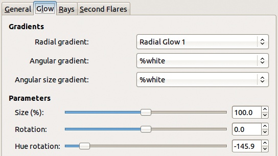
The last three parameters in this tab specify the size of the glow, the rotation angle of the angular gradient, and the color of the glow according to the hue circle.
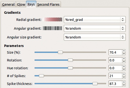
The number and pattern of the rays can be adjusted using the Rays tab (Figure 17-91). As in the Glow tab, the radial, angular, and angular size gradients determine the color, wrapping pattern, and radius of the Rays, respectively. The parameters below also have the same effect as those in the Glow tab. The number and thickness of the spikes can also be changed. Experiment with the number of spikes: A large number will lead to an interesting moiré effect.
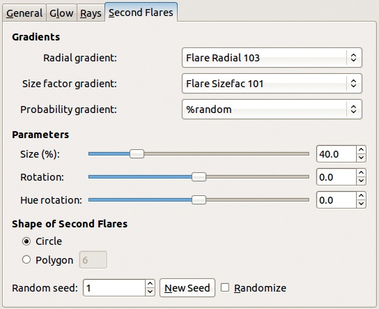
The parameters of the secondary flares can be specified using the Second Flares tab (Figure 17-92). The three gradients and the three parameters below have the same meaning as they do in the Glow tab and the Rays tab, except that PROBABILITY GRADIENT specifies the position of the second flares, rather than the radius. The shape of the Second Flares can be a circle or a polygon with three or more sides, or it can be a straight line, if the number of sides is set to 1. The RANDOMIZE button uses a random number to randomize everything. However, if you input a random seed, the effects are reproducible (the same seed always produces the same effect). The NEW SEED button generates a new seed.
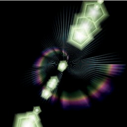
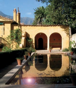
Figure 17-93 shows an example of a custom-made Gradient Flare.
Lens Flare simulates the effect of the sun striking the objective lens of a camera.
In the dialog, only one parameter can be changed: the position of the flare effect. The position can be set by clicking the preview or by changing the coordinates. You can also hide the cross that shows the position if you like, although this has no effect on the result. There is currently no way to change the size, shape, or hue of the lens flare.
Figure 17-94 shows the result of the Lens Flare filter.

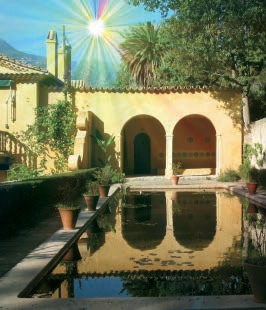
Lighting Effects is a complicated filter. As the name implies, it can be used to generate lighting effects in an image, such as that of a lamp light. In addition, it can be used to bump the image to create relief, and it can be used to simulate complicated reflections using an environment map. This filter would therefore also fit in the Map submenu. We demonstrate this complex filter on the image shown in Figure 17-85.
The Lighting Effects filter dialog has five tabs. Figure 17-95 shows the first one: the Options tab. If the INTERACTIVE button is checked, the light position can be changed by dragging the blue dot in the preview on the left. The DISTANCE slider sets the height of the light above the image relative to the image center. The position and the distance both contribute to the light effect, as you can see if you adjust each in turn. The dialog also contains a checkbox that allows you to create a new image with the effect, rather than altering the original image. An example of Lighting Effects, for which we adjusted parameters only in the Options tab, is shown in Figure 17-96.
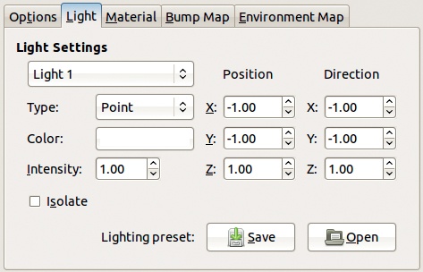
The Light tab (Figure 17-97) contains parameters for six different light sources. These parameter settings can be saved in a file for later use. Each source has the following options:
TYPE can be set to POINT, DIRECTIONAL, or NONE. NONE turns the selected source off, reducing the number of light sources. There can be anywhere from zero to six active light sources at the same time.
COLOR is set with the standard Color chooser.
INTENSITY changes the brightness of the light source and can be set to a number from [0 to 100].
POSITION is set relative to the center of the image and can be adjusted in the X, Y, and Z directions to any number from [–2 to +2]. POSITION is only active when the POINT type is selected.
DIRECTION is the same as POSITION, but it affects the direction of the light source and is only active when the DIRECTIONAL type is selected.
ISOLATE, if checked, alters the preview so that only the light source being set is shown.
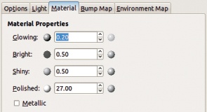
The Material tab (Figure 17-98) contains settings for five characteristics of the image surface. Each of them can be set to any positive value, or to zero, but usually values less than 1 work best for the first three:
GLOWING sets the intensity of areas that are not directly lighted.
BRIGHT sets the intensity of areas that are directly lighted.
SHINY sets the highlight intensity.
POLISHED sets the highlight focus: For low values, the highlight is wide; for high values, it’s more focused.
METALLIC, if checked, simulates the effect of a metallic surface.
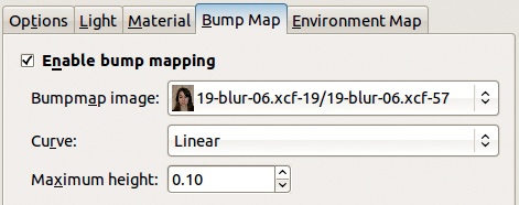
The Bump Map tab (Figure 17-99) can be used to add a bump map based on a different picture. The other image must be the same size as the image being transformed, and it must be open in GIMP when the filter is called. Only its Value channel is used to create the bump map, so it doesn’t matter whether it’s a grayscale or a color image. If the ENABLE BUMP MAPPING box is checked, a bump map image can be chosen. The response curve can be LINEAR, LOGARITHMIC, SINUSOIDAL, or SPHERICAL, and the relief can be controlled by adjusting the MAXIMUM HEIGHT field.

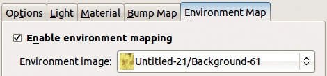

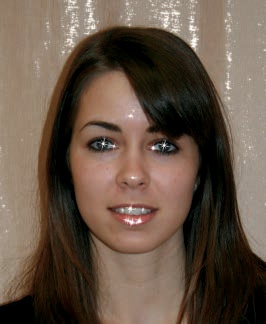
Figure 17-100 shows the result of the Lighting Effects filter with bump mapping enabled and the parameters shown in Figure 17-99. The bump map image is the portrait from Figure 5-44.
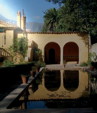
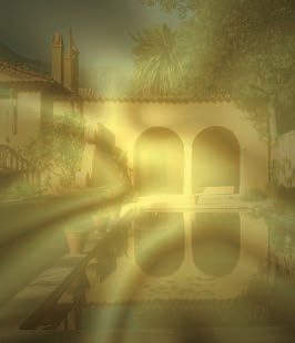
In the Environment Map tab (Figure 17-101) you can choose the Environment image, which must be an RGB image already open in GIMP. There are no other parameters. In our example, we used Figure 17-102. Figure 17-103 shows the result.

Sparkle adds star-like sparkles to the lightest points in the image, based on a set threshold.
The dialog is shown in Figure 17-104. There are several parameter sliders:
LUMINOSITY THRESHOLD [0 to 0.1]: Small values lead to fewer sparkles, while large values lead to more sparkles.
FLARE INTENSITY [0 to 1] specifies the width of the central spots.
SPIKE LENGTH [1 to 100] alters the length of the sparkles’ spikes.
SPIKE POINTS [0 to 16] determines the number of spikes on each sparkle.
SPIKE ANGLE [–1 to 360] specifies how the angle of the first large spike is generated with regard to the horizontal axis. If the value is –1, the angle is random.
SPIKE DENSITY [0 to 1] is the percentage of visible sparkles. A set number are generated by the filter’s algorithm, but only a subset will actually appear on the image, based on the density setting.
TRANSPARENCY [0 to 1] determines the opacity of the sparkles.
RANDOM HUE [0 to 1] changes the hue, unless the color is set to NATURAL (the color in the image where the sparkle was placed).
RANDOM SATURATION [0 to 1] operates in the same way as RANDOM HUE, except that it alters the saturation.
There are also three checkboxes:
PRESERVE LUMINOSITY applies the luminosity of the brightest pixels in the image to the center of the sparkle, which makes the sparkles almost invisible except in the lightest areas of the image.
INVERSE generates dark sparkles in the darkest parts of the image.
ADD BORDER generates an image border of sparkles. Try creating an image border with the Spike angle set to –1.
Finally there is a set of three radio buttons to choose the color of the sparkles: foreground, background, or natural (i.e., the color of the brightest—or darkest, if INVERSE is selected—point where the sparkle is drawn).
Figure 17-105 shows the result.
Supernova adds a large spiky star that is vaguely similar to a supernova. In the dialog, shown in Figure 17-106, you can move the center of the supernova by setting the coordinates or by clicking the preview. If the SHOW POSITION box is checked, crosshairs are also shown. Here are the other parameters:
COLOR is the base color, and clicking the box brings up the Color chooser.
RADIUS [1 to 100] specifies the size of the supernova’s central circle.
SPOKES [1 to 1024] is the number of 1-pixel-wide spikes extending from the supernova’s center.
RANDOM HUE [0 to 360] randomizes the spike colors.
The result of Supernova is shown in Figure 17-107.
Drop Shadow adds a drop shadow to an image or a selection without altering the contents of the image or generating a background layer. You can choose to add a background layer if Drop Shadow is applied to the full image.

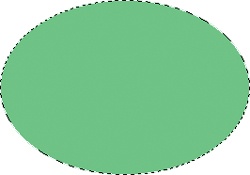

We built a simple green ellipse, shown in Figure 17-108, to demonstrate this filter.
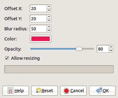
The dialog is shown in Figure 17-109. The first three parameters set the position and width (called BLUR RADIUS) of the drop shadow. Below that is COLOR, which brings up the Color chooser, and then OPACITY, which sets the opacity of the new layer built by the filter. If the ALLOW RESIZING box is checked, the filter can enlarge the image if necessary once the shadow has been added.
Figure 17-110 shows the result.
Perspective applies a shadow with perspective to an image or selection.
In the dialog, shown in Figure 17-111, you can set the ANGLE [0 to 180] between the light source and the target. If it’s less than 90°, the shadow is on the right; otherwise it’s on the left. The RELATIVE DISTANCE OF HORIZON [0.1 to 24.1] changes the distance of the horizon line relative to the height of the selection. The RELATIVE LENGTH OF SHADOW works the same way, but the shadow cannot extend beyond the horizon. The BLUR RADIUS [0 to 1024] is applied to the edges of the shadow. The OPACITY is that of the new layer that’s created. Finally, you can set the INTERPOLATION algorithm and allow or disallow image resizing.


The result is shown in Figure 17-112.