
Animating with Bones
When animating with bones, it is important to remember that at frame 0, you are only in setup mode. Changes you make to the bone structure during setup mode don’t affect the keys or animation. However, if you alter the skeleton at any frame other than 0, then a set of keys will be created for the change. Working with keys and the Timeline palette is covered in more detail in Part IV, “Animating in Anime Studio.”
Note
Any bone movement changes made with the Manipulate Bones tool (Z) while at frame 0 will automatically be reset when another tool is selected.
Moving Bones
When any frame except frame 0 is selected, moving, scaling, or rotating bones will result in a new key being added to the Timeline. Moving a bone as part of an animation will cause all the bound points to be stretched away from the rest of the object, as shown in Figure 27.1.

Scaling and Rotating Bones
When you begin to animate a bone by moving to a frame other than frame 0, the Scale Bone tool (S) becomes active and available. Dragging on a bone with this tool causes the length of the bone to increase, which results in the object being stretched to accommodate the new length, as shown in Figure 27.2.

The Rotate Bone tool (R) rotates the bone tip around its base.
Note
When animating bones, the Rotate Bone tool (R) works the same as the Manipulate Bone tool (Z).
Resetting Bones
If you change your mind about the animation of a single bone at a specific key, you can use the Bone, Reset Bone menu command to return the bone’s position and orientation to its original location as defined by the setup found in frame 0.
If you want to reset all bones to the default setup, you can use the Bone, Reset All Bones menu command.
Locking Bones
When the Select Bone tool (B) is selected, the Options bar at the top of the working area includes an option to Lock Bone. If you enable this option, the bone becomes frozen in its current position and remains there until you uncheck the Lock Bone option. This option can also be animated.
Handling Overlapping Fills
When a filled object that is being controlled by bones is bent back on itself, the overlapped sections will be cleared of any fill, leaving a gap in the object, as shown on the leg in Figure 27.3. This can be fixed by splitting the single filled object into two filled objects.

To eliminate an open gap created by overlapping filled sections, follow these steps:
1. | Open the Leg with bones.anme file from the Chapter 27 folder on the CD. This file shows a simple set of legs with bones added to the legs for controlling their movement. If you select the Manipulate Bones tool (Z) and bend the leg backward, the fill overlaps itself, thereby producing an empty gap. |
2. | Select the right leg layer in the Layers palette and hide the left leg and left leg bone layers. Then choose the Add Points tool (A) and draw a new line that separates the leg into two pieces. Make sure the Auto-Weld option is enabled so that the new line is connected to the existing lines. |
3. | Select the Select Shape tool (Q) and click on the leg’s shape to select it. Then click the Copy button in the Style palette to save the existing fill color. |
4. | With the leg shape still selected, select the Edit, Clear menu command to remove the fill from the existing leg. |
5. | |
6. | Repeat step 5 for the lower leg shape. |
7. | Select the Hide Edge tool (H) and click the line that separates the two leg shapes to remove its stroke. |
8. | Select the left leg bone layer and delete it from the Layers palette. Then select the right leg bone layer and click the Duplicate Layer button in the Layers palette and rename the new layers “left leg bone” and “left leg.” |
9. | Select the Manipulate Bone tool (Z) and drag the lower leg bone until the leg bends over itself, as shown in Figure 27.4. This time there is no empty gap. |

Setting Bone Constraints
Another option that is enabled when the Select Bone tool (B) is selected is the Bone Constraints button. This button opens the pop-up dialog box of options shown in Figure 27.5. The Angle Constraints option lets you set minimum and maximum rotations that the bone can make. This provides a way to limit the movement of the selected bone.
Figure 27.5. Bone Constraints dialog box.

When a constraint is applied to a bone, a red constraint line is placed at the bone joint to mark the bone’s limits, as shown in Figure 27.6.

To constrain a leg bone so that it doesn’t move unnaturally, follow these steps:
1. | Open the Constrain leg bone.anme file from the Chapter 27 folder on the CD. This file shows a simple set of legs with bones added to the legs for controlling their movement. If you select the Manipulate Bones tool (Z) and bend the lower leg bone forward, the leg moves in an unnatural way, as shown in Figure 27.7. |
2. | Click the Select Bone tool (B) and select the lower leg bone. Then click the Bone Constraints button at the top of the Working Area and enable the Angle Constraints option. When the Angle Constraints option is enabled, two lines are shown at the base of the selected bone to show the current constraints. |
3. | Change the Min/Max values to −130 and 20. The constraint lines are updated in the Working Area. |
4. | Select the Manipulate Bone tool (Z) and drag the lower leg bone to test the resulting constraints. If they don’t look right, adjust the constraint values until the limits are correct. Figure 27.8 shows the leg being bent to one of its constraint limits. |


Using Control Bones
Even more powerful are the options to select a control bone to control the angle, position, or scale of the selected bone. The value field to the right of the selected control bone is a multiplier that amplifies the affected change. This multiplier value can be set to 1 for a movement that is equal to the control bone, to 0.5 for movement that is half the control bone, to 2.0 for movement that is double the control bone, or even -1 for movement that is opposite the control bone.
Tip
The control bones will only work for named bones.
The two values next to the Position Control Bone option affect movement in the X direction and in the Y direction separately.
To make the rotation of one bone control the rotation of another bone, follow these steps:
Tip
When defining control bones, make sure that the control bone is not parented to the bones it is controlling.
1. | Open the Constrained clock.anme file from the Chapter 27 folder on the CD. This file includes a simple clock with large and small hands that are bound to rotate with the clock hand bones. The hands are set to 12 and 3. |
2. | Click the Select Bone tool (B) and select the large hand pointing to 12. In the Options bar, type in the name “large hand.” Then select the small hand pointing to the 3 and name it “small hand.” |
3. | With the large hand selected, click the Bone Constraints button in the Options bar. Click the Angle Control Bone drop-down list and select the Small Hand option and set the value to 12. Then close the Bone Constraints dialog box. |
4. | Select the Manipulate Bone tool (Z) and drag the tip of the small hand to rotate it around the clock. The large hand rotates along with the small hand, only it spins 12 times as fast just like a real clock, as shown in Figure 27.9. |

To make the position of the hand bone control the kite’s position, follow these steps:
1. | Open the Flying kite.anme file from the Chapter 27 folder on the CD. This file includes a simple project with a kite and the hand of a person flying the kite. Bones have been added to the kite and the person’s hand. |
2. | Click the Select Bone tool (B) and select the kite bone and name it “kite bone.” Then select the small hand, and name it “hand bone.” |
3. | With the kite bone selected, open the Bone Constraints dialog box by clicking the button on the Options bar. For the Position Control Bone, select the hand bone option and set the position values to 10 and 6. |
4. | With the bone layer selected, drag the Time Slider to a frame other than frame 0; then choose the Translate Bone tool (T) and drag the hand bone around. The kite will move to follow the hand only to a greater extent, as shown in Figure 27.10. |

Using Bone Dynamics
The task of animating usually focuses on the main, or primary, motions such as the legs and feet moving when a character walks, but realistic motion can be enhanced by looking for secondary motions like a ponytail swinging back and forth and the jostling of a backpack. These types of motions can be enabled by turning on the Bone Dynamics feature in the Bone Constraints dialog box.
After the Bone Dynamics feature is enabled, all child bones will react automatically with secondary motion when the parent bone is moved. For example, when a dog wags its tail back and forth, the bones at the end of the tail will rotate beyond the small rotation of the parent, causing a wagging effect when dynamics are enabled. The bone chain in Figure 27.11 consists of simply moving the top bone back and forth. Because Bone Dynamics is enabled, the children bones swing back and forth with momentum.

Bone dynamics are controlled by three values:
Torque Force: This is the force applied to the child bone when the parent bone changes direction when moving.
Spring Force: This is the force applied to the child bone when the parent bone changes its rotational direction.
Damping Force: This is the force that limits the motion of the child bone, causing its secondary motion to die out more quickly, like a shock absorber.
To endow the kite’s tail with dynamic bones, follow these steps:
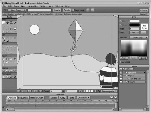
1. | Open the Flying kite with tail.anme file from the Chapter 27 folder on the CD. This file is an extension of the previous tutorial. For this project, the kite has been given a tail and four new bones to control the tail’s movement. The tail bones are parented to the main kite bone. |
2. | Drag the Time Slider to frame 1 to see the kite, its tail, and the tail’s bones. Then select the bone layer in the Layers palette. |
3. | Choose the Select Bone tool (B) and select the first tail bone. Open the Bone Constraints dialog box and enable the Bone Dynamics option. Set the Torque Force to 2, the Spring Force to 2, and the Damping Force to 1. Repeat this step for each of the tail’s bones. Then close the Bone Constraints dialog box. |
4. | Select the Transform Bone tool (T). Select and move the hand bone to the left of the working area. Then drag the Time Slider to frame 12 and move the hand bone to the right of the working area. This automatically creates the necessry keyframes to animate the kite, but it also causes the tail to dynamically whip back and forth as the kite moves. Create some additional keyframes for the kite’s movement. |
5. | Click the Play button in the lower-left corner of the main window to see the resulting animation. The kite tail whips around as the kite moves, as shown in Figure 27.12. |
Offsetting Bones
When animating complex bone skeletons that have a lot of bones, it can sometimes be tricky to identify where all the bones and their bound layers are located. The Bone Offset tool lets you enter a mode that defines the beginning positions of all the bones at frame 1. These positions can be different from the bone positions at frame 0.
So using the Bone Offset tool, you can position the bones exactly where they need to be for the animation, and then using frame 0, you can place the bones where they are organized and easy to select with gaps between them.
Note
The Bone Offset tool is only available when the Timeline is set to frame 0.
One common way to set up a character to work with bones is to place each of the different body parts separate from one another, as shown for the default Winsor character in Figure 27.13. Once each of the independent layers is bound to a set of bones and the bone strength areas are set, you can use the Bone Offset tool to position each of the body parts where they should be for animating, as shown pieced together in Figure 27.14.


After the Offset Bone tool is used to position the body parts, the character will automatically assume these positions when the Manipulate Bones tool (Z) is active at frame 0 or whenever a non-0 frame is selected. When any other tool is selected at frame 0, the body parts will move to their separated state. This provides a way to work with the bones either together or apart.