
Warping with Bones
There are a couple unique ways to use bones to control the warping of a bound layer. Once a layer is bound to a bone system, the bones can be manipulated to create a warp field or to define how the object moves. Although layer warping can be accomplished using a chain of bones, you’ll have more control over the warping by using a set of independent bones that aren’t parented to one another.
To create a set of independent bones, you simply need to click the background with the Select Bone (B) tool to deselect the current bone after each bone is created. You can check to see if any bones are parented by selecting the Reparent Bone (P) tool. Any parented bones will show a red arrow from the child bone to its parent. To remove any parenting, just select the bone that has a parent and click the background away from the other bones with the Reparent Bone tool.
Creating a Warp Field
The key to defining a warp field is to place the bones at frame 0 to represent an undistorted view of the layer that you want to distort. The bones should be placed so that the bone’s base is located at the rotation point for the warp. Then at frame 1, rotate the bones to create the warp. The change between the bone’s orientation at frame 1 will automatically be applied to any sublayers under the bone layer.
Note
This technique is similar to the technique presented in Chapter 22, “Adding Image Layers.”
To warp a bone sublayer, follow these steps:
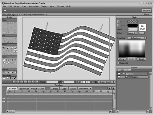
1. | Open the American Flag.anme file from the Chapter 27 folder on the CD. This file is a simple image layer of a flag. |
2. | Click the New Layer button in the Layers palette and create a new bone layer. Select and drag the image layer and drop it on the new bone layer to make it a sublayer. |
3. | Select the bone layer, select the Add Bone (A) tool, and drag from the lower-left corner of the flag to the top of the flag to create a single vertically-oriented bone. Choose the Select Bone (B) tool and click away from the other bone to deselect the first bone. Then with the Add Bone tool, drag from the lower-right corner to the top of the flag to create a second vertically oriented bone. |
4. | Set the frame to frame 1 in the Timeline palette and choose the Manipulate Bones (Z) tool and drag the tip of each bone to the right. Figure 27.15 shows the resulting warped image. |
In addition to changing the bone’s orientation by rotating the bones, you can also move the bones from their original position to stretch the image in the direction of the bone’s movement. The Bone Strength can also be adjusted to change the area around the bone that is affected by the bone’s change.
Defining a Motion Path
Since the Bone sublayer will automatically be warped with the bones, you can also use a set of bones to create a motion path for the sublayer to follow. The key is to lay out the original set of bones is a straight line in frame 0 and animate the movement of sublayer with the Translate Layer tool following the set of bones. Then in frame 1, you can move the bones, and the moving sublayer will be distorted to follow the manipulated bones.
Tip
This technique will work with a chain of parented bones or with a set of individual bones. The only difference is that the unparented bones will give you more control over the bone’s placement.
To use bones to define a motion path, follow these steps:
1. | Open the Following a path of bones.anme file from the Chapter 27 folder on the CD. This file shows a simple amoeba character. |
2. | Click the New Layer button in the Layers palette and create a new bone layer. Select and drag the vector layer and drop it on the new bone layer to make it a sublayer. |
3. | Select the bone layer, select the Add Bone (A) tool, and drag from the middle of the character to the left, creating a chain of six parented bones that extend in a straight line to the right edge of the working area. |
4. | Select the vector layer and drag the Time Slider in the Timeline palette to frame 30. Then move the character across the screen to the right side of the screen with the Translate Layer tool. |
5. | Select the bone layer and drag the Time Slider to frame 1. With the Manipulate Layer (Z) tool, change the orientation of the bones to create a motion path for the character to follow, like the one shown in Figure 27.16. |
6. | Click the Play button to see the character follow the path defined by the bones. |
