Creating a Stroke
If you draw a shape or a line with the Auto-Stroke option disabled, you’ll see a simple line without any style applied to it. This line will not be visible in the final render, but you can convert this default line into a line with a style applied or a default shape into a shape with a fill using the Create Shape tool (U).
To convert a default line or shape to one with a fill and stroke, simply select the line or shape with the Create Shape tool. The line or shape will turn red when selected, as shown in Figure 13.7. Then press the Spacebar or click the Create Shape button in the Options bar, and the current fill and stroke styles as defined in the Style palette are applied to the selected object.
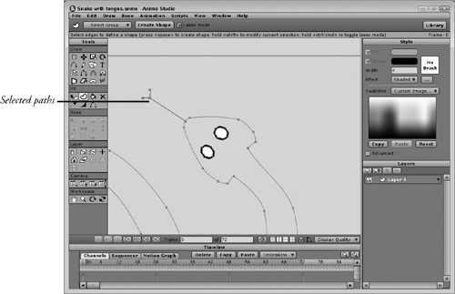
When selecting a shape, you need to select all the curves that make up the shape in order to apply a fill to it. If you click any part of the closed shape’s curve, then the entire shape, including its fill, is automatically selected and the fill is shown as a checkerboard pattern. If the curve isn’t a closed shape, then the curve is displayed red, and if the curve is thick enough, the checkerboard pattern is displayed on the curve, as shown in Figure 13.8.
When you want to select only a portion of the shape’s curve, just drag over a selection area that includes the points on either end of the segment you want to stroke, and they will be selected. If you hold down the Ctrl/Cmd key or enable the Lasso Mode option in the Options bar, the mouse cursor changes to a lasso that you can use to encircle the segments you want to choose.
To create a road using strokes, follow these steps:
1. | Select the File, New menu command to open a blank project. |
2. | In the Style palette, click the black color swatch to change the fill color to black and right-click the white color swatch to change the stroke color to white. Then select the Rectangle tool (E) and drag in the working area to create a black rectangle. |
3. | Select the Add Points tool (A) and draw a dashed line down the center of the black rectangle. When creating this line, create a larger section with two points farther away from each other followed by three points fairly close together before creating another large dashed section. You can enable the grid and use grid snapping to make the dashes consistent. |
4. | In the Style palette, right-click the bright yellow color swatch to change the stroke color and set the Line Width value to 16. Then select the Create Shape tool (U), click the first point of the large dashed section, hold down the Shift key, and select the points on either side of the large dashed section. When all the dashed sections are selected, press the Spacebar to apply the current stroke color and width. This colors the larger dashed sections yellow and increases their width. |
5. | Select the Rotate Layer XY tool in the Layers tool section and drag to change the perspective of the road so it recedes into the distance, as shown in Figure 13.9. |

Caution
If you look closely at the road example, you’ll see that the perspective effect isn’t applied to the dashed center line.
Changing Line Width
By default, line thickness is defined using the Line Width value in the Style palette for new stroked lines. This specified value remains constant for the entire curve, but if you select a specific point, you can use the Line Width tool (W) to change the thickness of the line entering and leaving the selected point by dragging the mouse. You can also set the thickness value using the Width field in the Options bar.
If multiple points are selected, then the line thickness is changed for all selected points. However, if the line has no stroke applied, then the Line Width tool does nothing. Figure 13.10 shows the line width around the front point of the arrow shape being increased. Notice how the width gradually decreases as it gets closer to the adjacent points.

Caution
Once the line width for a point has been adjusted with the Line Width tool, the point will no longer be included when a new stroke width is applied to the entire curve. Adjustments made to line width with the Line Width tool take precedence over the Line Width value in the Style palette.
Note
Another way to alter the line width is with the Reset Line Width and the Random Line Width commands in the Draw menu. These features are covered in Chapter 9, “Using the Drawing Tools.”
Applying Multiple Stroke Widths
When playing with line widths, Anime Studio has an interesting ability to apply multiple line widths and colors to a single curve. This technique doesn’t work for fills, but it can be applied to open curves that have a stroke. To use this technique, you’ll need to apply a stroke with a larger line width value to a curve, alter the color and decrease the line width value in the Style palette, and reapply the stroke. The first larger color will remain and the small line width will also be visible. This technique will also work if you apply a larger semi-transparent color on top of a smaller line width.
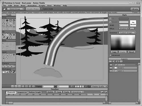
To create a rainbow by applying multiple line widths to a curve, follow these steps:
1. | Open the Rainbow in the forest.anme file from the Chapter 13 folder on the CD. This file includes the forest background with a single curved line added to a new layer. |
2. | Right-click the purple swatch in the Style palette to select it as the stroke color. Set the Line Width value to 40 and select the Create Shape tool (U). Then click the rainbow curve and press the Spacebar to apply the stroke. |
3. | Click away from the curve to deselect the stroke; then right-click the blue swatch in the Style palette to select it as the stroke color. Set the Line Width value to 35 and select the Create Shape tool (U). Click the rainbow curve and press the Spacebar to apply the stroke. Note If you don’t deselect the stroke each time, the new color will be applied immediately to the curve. |
4. | Repeat step 3 for cyan, green, yellow, orange, and red while decreasing the line width by 5 each time. The resulting rainbow is shown in Figure 13.11. Note To create a more realistic rainbow, you’ll want to make the colors semi-transparent, which can be done by adjusting the alpha value for each color. Chapter 15, “Setting Object Style,” shows how to do this. |
Using the Scale Compensation Setting
When adjusting the thickness of a curve, you should be aware that when the layer that contains variable width lines is rotated or tilted, the line width may change with the rotation. There is a setting in the Layer Settings dialog box for controlling whether the stroke thickness scales with the objects as the layer is rotated. When the Scale Compensation option is enabled in the Layer Settings dialog box, all stroke widths are adjusted with the rotating layer. When this option is disabled, the line width stays consistent despite the rotation.
Figure 13.12 shows this effect by revisiting the road example done earlier in this chapter. It shows the road with the Scale Compensation option disabled. Notice how the center dashed line remains the same thickness along the entire road.

Note
The Scale Compensation option has no effect on the Perspective Points tools. Line width is always constant when using these tools.
Hiding Edges with the Hide Edge Tool
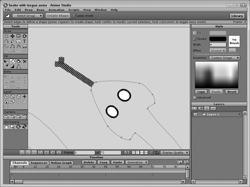
Using the Delete Shape tool, you can remove the entire stroke from the selected shape, but if you want to only remove the stroke from a single segment, you can use the Hide Edge (H) tool, located in the Draw section of the Tools palette. This tool selectively removes the stroke from the single segment you click on. Figure 13.13 shows a thick stroke applied to the arrow shape, but the line that separates the arrowhead from the arrow body has been hidden using the Hide Edge tool.

Raise or Lower a Shape’s Stacking Order
Shapes are stacked on top of one another in the order they are created, so the first object created becomes the bottom object and is obscured by all subsequent objects that overlap it. But you can change the stacking order of objects using the commands found in the Draw menu.
Note
Stacking order only affects objects on the same layer. All objects on a higher layer will appear on top of the objects on a lower layer regardless of their stacking order.
The Lower Shape and Raise Shape commands in the Draw menu are only available when a shape object is selected (and the checkerboard pattern is visible). Selecting either of these commands changes the current object’s order in the stack even if there isn’t an overlapping object. You can also use the Raise to Front or the Lower to Back commands to move the current shape to the very front or the very back of the stacking order.
Tip
If you hold the Shift key down and press the down arrow, you can move the current shape to the bottom of the stack; holding the Shift key down and pressing the up arrow moves the current shape to the top of the stack.
Figure 13.14 shows some text added to the sign. Even though the text is on the same layer, it is visible because its stacking level is higher than that of the sign. The sign post, however, is at a lower stacking level so its top end is hidden behind the sign. Using the Draw, Raise Shape and Lower Shape menus, you could move the text in front of the sign or the sign post below the sign.

Note
If the fill or stroke color of an object is semi-transparent, then the objects underneath will be at least partially visible.
Selecting Obscured Shapes
Once an object’s shapes are filled, you can select the shapes with the Select Shape tool (Q) and move their stacking order up or back with the Draw menu. But if a shape is moved to the back of the stacking order and is obscured by another shape, it can be difficult to select with the Select Shape tool if you want to change its fill style. For these situations, you can use the Ctrl/Cmd+down arrow keys to select the obscured shape. When selected, the checkered pattern appears on the obscured shape.
To select an obscured shape with the Select Shape tool (Q), follow these steps:
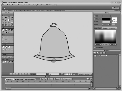
1. | Open the Bell.anme file from the Chapter 13 folder on the CD. This file shows a simple bell object with filled shapes and a ringer located inside it. |
2. | Choose the Create Shape tool (U) from the Tools palette and click one of the corner points of the interior ringer. Then hold down the Shift key and click all the points that surround the ringer. When a closed area is selected, the checkered fill pattern is displayed. |
3. | Change the fill color in the Style palette to black and press the Spacebar to apply the new color. The ringer appears on the outside of the bell since it was created after the bell. |
4. | |
5. | Click the ringer again with the Select Shape tool (Q). The bell shape is selected. Hold down the Ctrl/Cmd key and press the down arrow key. This selects the next shape just under where you clicked, which is the ringer. |
6. | Select a reddish-brown fill color and press the Spacebar to apply it to the selected ringer shape. |
7. | With the Select Points tool (G), click the points that make up the ringer and then move the ringer down with the Translate Points tool (T) so that it is just visible below the bottom of the bell, as shown in Figure 13.15. |