
Working with the Working Area
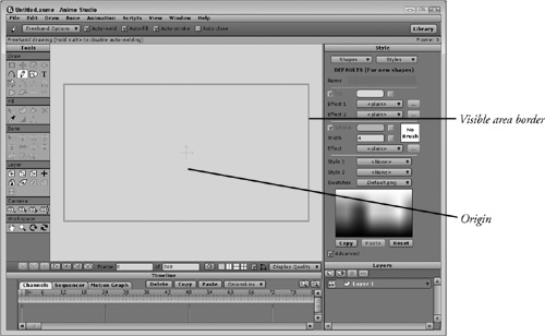
When a new working area is loaded, two crossing arrows are displayed at the center of the area. These arrows are called the origin, as shown in Figure 3.3, and they denote the center of the working area. It is about the origin that the current layer is scaled and rotated. All coordinate values are also measured from the origin. The Layer category in the Tools palette includes a tool for moving the origin.
Tip
The area outside of the visible region can be used as a holding area for objects that aren’t currently in the scene. Objects outside of this region are not rendered.
The working area also includes a blue rectangle that marks the edges of the visible region. Only objects contained within this visible region are visible in the final animation. You can change the size of the visible region using the File, Project Settings dialog box, which is covered later in this chapter.
You can hide the entire area and all objects outside of the visible region using the View, Show Output Only menu command (Ctrl/Cmd+J).
Navigating the Workspace
Even though the visible area is the only area that is rendered for the final output, you can use the entire working area for positioning and working with your objects. In order to access the area beyond the visible region, you’ll need to pan or zoom the workspace. The Tools palette includes four tools in the Workspace category, listed in Figure 3.4, for navigating the working area.
Figure 3.4. Workspace tools.

You can pan the working area using the Pan tool, which is found in the Workspace category of the Tools palette (it looks like a hand). Selecting the Pan tool lets you reposition the visible region by dragging with the left mouse button.
Tip
You can also pan the working area by dragging with the right mouse button, regardless of which tool is selected, or by holding down the Spacebar while dragging the mouse.
The Zoom tool (which looks like a magnifying glass) is used to zoom in and out of the working area by dragging the left mouse button left and right. This tool is located next to the Pan tool in the Workspace region of the Tools palette. The Zoom tool always zooms in straight to the center of the main window, regardless of where your mouse cursor is located. To zoom in on a particular object, you should first pan the working area so that the object is located in the center of the main window before zooming
You can control the exact place where the zoom takes place by dragging over the area that you want to zoom on if you enable the Zoom with Drag Box option in the Preferences dialog box. Once enabled, you can drag to specify a rectangular region to zoom in on.
Tip
You can also zoom in and out of the working area by dragging with the right mouse button while holding down the Shift key or by rolling the mouse scroll wheel back and forth. These shortcuts for zooming will work no matter which tool is selected.
Tip
Being able to pan and zoom with the mouse are the first shortcuts that you should memorize. They will allow you to quickly navigate the working area as you draw and work with objects.
Although not as important as panning and zooming, the Rotate Workspace tool (8) lets you spin the entire working area about the center of the main window. If you find it easier to draw vertical lines by dragging the mouse side to side, then you can rotate the working area to do this. Figure 3.5 shows a scene rotated to the side.

Tip
The shortcut for the Rotate tool is to hold down the Ctrl/Cmd key while dragging with the right mouse button. This shortcut works regardless of the selected tool.
The Orbit Workspace tool (9) lets you rotate the working area into 3D space causing the flat 2D drawings to be tilted at an angle, as shown in Figure 3.6. When rotating the project into 3D space, the visible region border disappears, but a blue view icon appears showing the 3D location of the default view. The Orbit tool can rotate 360 degrees about the center of the working area. The Orbit tool is especially helpful when you have some 3D objects added to your scene because it lets you rotate about them in 3D space seeing them from all angles. Holding down the Alt/Opt key while dragging with this tool moves the camera closer or farther from the center.

Resetting the View
When any of the Workspace tools are selected, you can return the view to its default size and position by clicking the Reset View button located in the Tool Options bar. This same feature can be accessed using the View, Reset menu command or by pressing the Escape or Home keyboard keys. This button centers the entire visible region within the main window.
Tip
The Home key is another good shortcut to learn because it lets you get back to the default view quickly.
Using Grids
The Enable Grid menu and the Grid Spacing menus are located in the View menu. Selecting the Enable Grid menu makes an infinite grid appear in the main window, as shown in Figure 3.7. You can change the density of the grid using the Grid Settings menu, which opens the Grid Settings dialog box, shown in Figure 3.8. The Grid Spacing value is measured in pixels.

Figure 3.8. Grid Spacing dialog box.

Note
Grids are only available in Anime Studio Pro.
Grids are great for visually lining up points when drawing on a vector layer, but they offer more flexibility than just visually lining up objects. If you begin drawing curves and shapes with the grid enabled, then any points you create will snap automatically to the closest grid point. This is convenient if you want to draw precise shapes such as perfect squares and circles. But it can be annoying if you want your objects to have a more freehand look to them.
Caution
If you zoom way in on a snapped point, you’ll notice that the point doesn’t line up exactly with the grid and that all curves are slightly bowed, but the spacing is consistent so all snapped points will be equally spaced and at the normal view these odd effects aren’t noticeable.
You can disable grid snapping while keeping the grid active is with the View, Disable Grid Snapping menu command. This is a simple toggle command that can be on or off. When enabled, snapping to grid points is suspended.
If you have an existing freehand curve or object that you want to snap to the nearest grid point, you can use the Draw, Snap to Grid menu command (Ctrl/Cmd+G). If you’ve drawn a freehand curve, be cautious in using the Snap to Grid command because it could distort the curve you’ve drawn, as shown in Figure 3.9, which shows a smooth freehand letter on the left and the same letter on the right after the Snap to Grid command was used.

You should also be aware that the grid will move with the current layer. If you want to have a grid that doesn’t move, which is useful as a visual reference when animating, then you can simply create your own grid on a lower layer or screen capture the grid and load it into an image layer. By placing a grid image or drawing on its own layer, it will stay stationary as the other layers move.
Enabling Multiple Views
To the right of the Mute Sound toggle at the bottom of the main window are four boxes. These icons are used to show multiple views of the scene in the working area. The enabled option is highlighted darker than the other options. The four options, from left to right, are as follows:
Single View: Displays a single view in the main window.
Side by Side: Displays two vertically stretched views in the main window.
Over and Under: Displays two horizontally stretched views in the main window.
Four-way View: Displays four views in the main window, one in each corner.
Figure 3.10 shows the main window divided into four separate views with the Four-way button. Each view can be configured and navigated independently of the others.

When multiple views are available, the current view is indicated by the view that has a gray border around it. The display quality options, covered in the next section, only apply to the current view window. When an animation is played, it is played equally in all windows. The grid and the Fast Buffer display quality option also apply to all view windows.
Using multiple views is helpful when you are working in several different places at once. For example, if you have a character open, one view can focus on the head and another on the hands. The drawback to this is that if you switch back to a single view and then return to the four-window view, all of the zoomed views are reset each time you reopen the four-view window.
Displaying Paths
To the right of the Multiple View icons is a single checkbox for displaying or hiding Construction Curves, which are also known as paths. When enabled, all the lines and points for the selected object are displayed allowing you to move and edit them. When disabled, these paths are hidden showing only the object and its fill. Figure 3.11 shows the default project with paths enabled.

New Feature
The checkbox in the main view window to turn paths on and off is new to Anime Studio 6.
Note
Toggling paths on in the main window is the same as enabling the Paths option in the Display Quality pop-up dialog box.
Changing the Display Quality
At the bottom-right corner of the main window is a pop-up set of options for setting the display quality, as shown in Figure 3.12. As your scene gets more and more complex, using these options makes it easy to find and select specific elements, and it also speeds the redrawing of the scene.
Figure 3.12. Display Quality options.

The buttons on the left are presets that selectively enable several of the options on the right. The preset buttons include Wireframe, Low, Medium, High, and Preview. The Wireframe preset enables only the Paths option, the Low preset adds Fills and Images, the Medium preset shows all the images as smoothed and adds in Strokes and Masking, the High preset adds the Shape Effects, Transparency and Brush options, and the Preview preset hides the Paths option. This shows the scene without any editing controls, just as if the scene were output.
The available options in the Details section include:
Fast Buffer: Enables the fast method for redrawing the scene, but note that choosing this option can result in inaccurate colors.
Paths: Displays all points and curves for vector layers.
Fills: Displays all the vector shape fill colors.
Strokes: Displays the outlines for all vector layers.
Shape Effects: Displays any applied effects added in the Style palette to a fill.
Images: Displays all imported images.
Smooth Images: Displays all images with alpha blending.
Masking: Displays all masking effects.
Transparency: Displays transparency.
Brushes: Displays all brush effects applied to strokes.
Antialiasing: Displays vectors without any jagged edges due to aliasing.
Figure 3.13 shows a character in the side-by-side view layout. The left view window has the Wireframe preset selected. This lets you work with the points, edges, and bones without any distractions. The right view window has the Preview preset selected, which shows the character without any bones.

Tip
You can close the Display Quality pop-up dialog box by right-clicking in the working area away from the dialog box.
Tip
Each layout pane can have its own Display Quality settings.
The Display Quality buttons are helpful when your project becomes more complicated, but it can also cause trouble if you forget about your current settings. For example, if you disable the Paths option, then any points or curves you draw in the working area won’t be visible even though they are created. This same problem happens if you draw a curve with the Add Points tool when the Preview display preset is selected.
Concerning the Transparency display option, this only applies to transparent vector objects. Image layers can be made transparent, but you’ll need to render the project in order to see transparent images. You can render the project with the File, Preview menu command (Ctrl/Cmd+R). One work-around for this is to save the image using the .PNG format with transparency. Transparent .PNG images will appear transparent in Anime Studio if the Smooth Images display option is enabled.
Note
Many of these same Display Quality settings are available for individual layers using the Current Layer pop-up list.
Enabling Video Safe Zones
When an animation sequence is displayed on a television set, the pixels at the edges of the display can appear distorted, blurred, or even chopped off. It would be tragic to have the opening text of your animation that says, “To Everyone, Hello,” end up with the last o chopped off, thus making your cheerful greeting into something offensive.
To prevent this, you need to keep any text or pixels you don’t want to lose in the center of the screen. To know exactly which areas are safe, you can enable the View, Video Safe Zones (Ctrl/Cmd+F) menu command. This shows the safe areas as two light brown rectangles, as shown in Figure 3.14. The inner rectangle shows the safe area for titles and the outer rectangle shows the safe area for action.

Note
The Video Safe Zones feature is only available in Anime Studio Pro.
Loading a Tracing Image
If you have a scanned, sketched image or a digital snapshot that you want to use as a template so that you can trace the artwork, you can use the View, Select Tracing Image (Ctrl/Cmd+Y) or the File, Import, Tracing Image menu command. This loads and centers the selected image within the main window and dims the image to allow you to trace it easily using the various drawing tools. Figure 3.15 shows an image loaded as a tracing image.

Note
The Tracing Image features are only available in Anime Studio Pro.
Tip
If you drag and drop an image onto the main window, a dialog box appears with options to make the image a Tracing Image, a New Image Layer, or to Cancel.
The background tracing image can be hidden using the View, Show Tracing Image (Ctrl/Cmd+U) menu command. This command toggles the tracing image on and off, but doesn’t remove it from memory.
Caution
Tracing images are not saved with the project file. If you save, close, and then reopen a file, you’ll need to add the tracing image again. Also, if you switch between different views using the layout buttons at the bottom of the main window, the tracing image is lost.
If you don’t want to use the Tracing Image feature, then you can create your own tracing layer by adding a vector layer above the image you want to trace, creating a large white rectangle and setting its Opacity setting to 75% in the Layer Settings dialog box. You’ll need to make sure that the Transparency setting in the Display Settings is enabled in order to see through the white rectangle. This method also gives you the option to move the image or the vector layer. It also gives you the chance to change the Opacity if the image is too dim.