
Guides can help us to position things within an image. A grid is another way to visualize placement. In fact, an image always has a grid, but it’s hidden by default. You can permanently change this setting, as described in Chapter 22. You can make the grid visible by using Image: View > Show Grid. Figure 10-12 shows the result. Note that this image is displayed with a zoom factor of 100%.
This grid has a mesh size of 10 × 10 pixels. When Image: View > Snap to Grid is checked, the mouse pointer always snaps to the intersection of two lines, even if it appears to be somewhere inside the mesh, as shown in Figure 10-13. You can see that the coordinates displayed in the status bar are both multiples of 10.


We can configure the grid by selecting Image: Image > Configure Grid. The dialog shown in Figure 10-14 pops up. We can change a number of parameters, which we’ll consider in turn.
The grid’s APPEARANCE is controlled by three parameters: LINE STYLE, FOREGROUND COLOR, and BACKGROUND COLOR. You have five choices for the LINE STYLE, as shown in Figure 10-15:
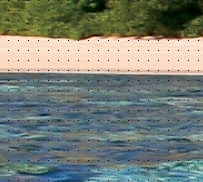
INTERSECTIONS (DOTS) is shown in Figure 10-16. The dots are one pixel wide, regardless of the image’s zoom factor. They can be hard to see.
INTERSECTIONS (CROSSHAIRS) is shown in Figure 10-17. The crosses are more visible than the dots, but they can be distracting.
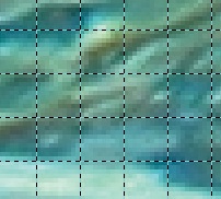
DASHED is shown in Figure 10-18. We increased the zoom factor to make the details visible. This line style emphasizes the lines in the grid, rather than the intersections.
DOUBLE DASHED is shown in Figure 10-19. Here again, we increased the zoom factor, so the lines are even more visible.
SOLID is shown in Figure 10-20. SOLID is the default style, shown here at an intermediate zoom factor.


The FOREGROUND COLOR is the color of the dots, crosshairs, or lines. In Figure 10-20 we changed this to green.
The BACKGROUND COLOR is used only with DOUBLE DASHED, as shown in Figure 10-19, where the background color is cyan.
The SPACING of the grid determines the size of the grid mesh. Choose a size in pixels or in whatever units you prefer. The size depends on the image resolution, as discussed earlier in this chapter. To create a rectangular mesh, break the chain below the counters before inputting the new size.

The OFFSET of the grid specifies where the first coordinates are placed. Initially the first coordinates are (0, 0) (i.e., in the top-left corner of the canvas).