
Whereas brushes and patterns are basically images, gradients are something different. The only way to build a new gradient is with the Gradient Editor (Gradients: Gradient Menu > Edit Gradient) or by clicking the bottom-left icon in the Gradients dialog. As with brushes, you cannot edit a gradient that does not belong to you. To edit an existing gradient, you first need to duplicate that gradient, and then you can edit the duplicate.
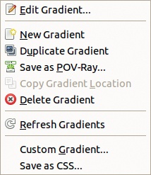
All of the gradient editing actions are available as buttons at the bottom of the Gradients dialog. Or you can select Gradients: Gradient Menu or right-click a gradient to open the Gradients dialog menu (see Figure 22-47). You can copy the path to the gradient in the clipboard and paste it in a text file. Choose CUSTOM GRADIENT to create an image containing only the current gradient. You can set the height and width of this image, which is useful for testing complicated gradients. And you can export the gradient to POV-Ray format if you’re working with Persistence of Vision Raytracer.
The gradients you build are exported with the suffix .ggr (for GIMP Gradient), a GIMP-specific format.
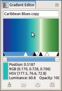
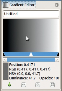
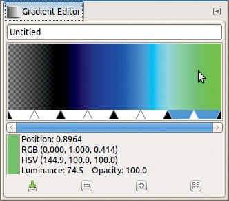
To try out the Gradient Editor, open the Gradients dialog, choose the gradient Caribbean Blues, and click Duplicate Gradient (or select Gradients: Gradients Menu > Duplicate Gradient). The dialog shown in Figure 22-48 opens. If you click a color in the gradient, the bottom of the window displays these options:
POSITION: Horizontal position within the gradient (0.0 = far left, 0.5 = center, 1.0 = far right)
RGB: The values in the red, green, and blue channels (with the range [0 to 1])
HSV: The hue (an angle in degrees) and the saturation and value (both as percentages)
LUMINANCE and OPACITY as percentages
The small rectangle displays the color of the gradient. The four buttons at the bottom of the dialog let you save the gradient, zoom in or out, or return to a set zoom factor such as Fit in Window.
Click the gradient image to set the foreground color or ![]() -click to set the background color. You can click and drag from the Toolbox color swatch to the Gradient Editor to change its colors in real time, but only the RGB values are displayed in the dialog.
-click to set the background color. You can click and drag from the Toolbox color swatch to the Gradient Editor to change its colors in real time, but only the RGB values are displayed in the dialog.
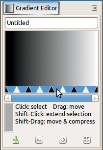
At the top of the Gradient Editor dialog, you can change the name of the gradient. Gradients are made up of a sequence of segments. Each segment is a smooth transition from the color on the left (marked by a black triangle) to the color on the right (marked by the next black triangle). The white triangles are similar to the Gamma triangle in the Levels tool: They don’t change the first and last colors, but they do change how the transition is done. In other words, the white triangle changes the shape of the answer curve.
To perform simple transformations on the gradient being edited, first widen the window. Next, double-click a segment between two black triangles to select it and make it blue. (To select a sequence of segments, ![]() -click on the last one.)
-click on the last one.)
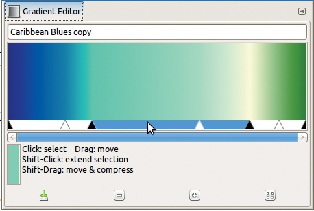
Once you’ve selected a segment, you can move the black triangles to extend, reduce, or move the segment. You can also move the white triangle to deform the answer curve in the segment or move the entire selected segment by adjusting its two black triangles simultaneously to compress or expand the neighboring segments, as shown in Figure 22-49. When you check the INSTANT UPDATE button, the effect is immediate; otherwise, it shows up when you release the mouse button.
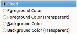
You can open the Gradient Editor menu (Figure 22-50) from the dialog menu or by right-clicking in the gradient in the dialog. This menu allows you to change the two colors that define a gradient segment. Figure 22-51 shows the menu that opens when you choose LEFT COLOR TYPE (the RIGHT COLOR TYPE menu is identical). FIXED mode is the default, and you select the endpoint color using one of the two entries in the Gradient Editor menu. Alternatively, you can choose to attach the color of one of the endpoints to the foreground or background color. The gradient you’re building then depends on these colors—like the first four (FG to BG) gradients that come with GIMP.
The endpoint color can have an Alpha channel. If you check an entry that includes “(Transparent),” the Alpha channel is 0 at the first endpoint and increases as it moves toward the other endpoint. Alternatively, click LEFT ENDPOINT’S COLOR (or RIGHT ENDPOINT’S COLOR) in the Gradient Editor menu, and you can use the Color chooser to change the value of the Alpha channel as you desire.

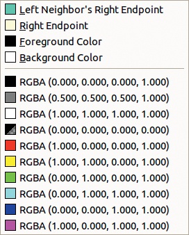
Selecting LOAD LEFT COLOR FROM (or RIGHT COLOR) in the Gradient Editor menu opens the menu shown in Figure 22-52. Here you can select neighboring colors in the gradient or choose from a set palette of 10 colors, which you can customize. To change to one of the colors on the preset palette, select SAVE LEFT COLOR TO (or RIGHT COLOR) to choose one of those 10 colors.
Alternatively, you can change gradient colors to colors in an image:
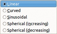
The next entry in the Gradient Editor menu, BLENDING FUNCTION FOR SEGMENT, opens the menu shown in Figure 22-53. Here, you can choose from five different left-to-right transitions for the current segment:
LINEAR is the default. The color changes steadily, and the point over the white triangle is a blend of the starting and ending color. For example, if the segment transitions from red to yellow, the point over the white triangle is orange.
CURVED makes the changes in color faster on the ends of the segment.
SINUSOIDAL, on the contrary, makes the color change faster in the middle (as set by the white triangle).
SPHERICAL (INCREASING) makes the color change faster on the left than on the right.
SPHERICAL (DECREASING) is the same, but the change is faster on the right.
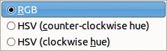
The next entry, COLORING TYPE FOR SEGMENT, opens the menu shown in Figure 22-54, where you can decide whether the transition between colors is made along the RGB or HSV space. If you look at the first four gradients when the foreground and background colors are actual colors, say blue and red, you can observe the difference between a gradient transitioning along the HSV model versus the RGB model.
The next entries in the Gradient Editor menu are as follows:
FLIP SEGMENT is the only action that can be reversed because the Gradient Editor does not have any undo capability.
REPLICATE SEGMENT makes a number of copies of the segment.
SPLIT SEGMENT AT MIDPOINT creates two segments from the current segment. The segments are split at the white triangle, and a new white triangle is placed at the center of each resulting segment.
SPLIT SEGMENT UNIFORMLY does the same, but it ignores the white triangle in the segment to be split, and you can choose the number of new segments.
DELETE SEGMENT deletes the whole segment or a selection within the segment. The segments on both sides of the deleted segment are enlarged to fill the space.
RE-CENTER SEGMENT’S MIDPOINT places the white triangle exactly in the middle of the segment.
RE-DISTRIBUTE HANDLES IN SEGMENT makes all triangles equidistant and is only useful when you’re selecting several segments.
BLEND ENDPOINTS’COLORS is active only when several segments are selected. An average of the right color of one segment and the left color of the other replaces the colors on all boundaries in the selection.
BLEND ENDPOINTS’OPACITY works the same as BLEND ENDPOINTS’COLORS but with opacity instead of color.
To help you understand the Gradient Editor’s many features, here’s an example showing how you can define a gradient with four segments.
Suppose the foreground and background colors are set to their defaults. In the Gradients dialog, click NEW GRADIENT, and the window shown in Figure 22-55 opens.
To define a gradient with four segments, select SPLIT SEGMENT UNIFORMLY from the dialog menu and change the slider value to 4. Then click SPLIT to get the result shown in Figure 22-56. This dialog is narrow, but you can enlarge it. You can also use the zoom icons at the bottom to magnify the dialog, but you won’t be able to see the entire gradient.
After splitting, all of the segments are selected. Carefully select the first segment from the left. Applying the LEFT COLOR TYPE and RIGHT COLOR TYPE, set the left endpoint type to FOREGROUND (TRANSPARENT) and the right endpoint to FOREGROUND. Now the first segment is entirely determined by the foreground color.
Next we change the colors of the three other segments. For each, set the left endpoint color to that of the LEFT NEIGHBOR’S RIGHT ENDPOINT and select any color you like for the right endpoint. The result is smooth transitions between the segments, as shown in Figure 22-57.
Now we’ll change the blending function for the segments: linear for the first, sinusoidal for the second, spherical (increasing) for the third, and spherical (decreasing) for the fourth. Finally, move the white and black triangles slightly, as shown in Figure 22-58. Remember, you can’t move the triangles independently in a selected segment.

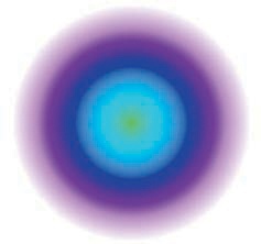
To test the new gradient, change the foreground color to purple, hexadecimal value 8f14e5. Create a new, white 400 × 400 image and apply to it, from the middle, a radial gradient in normal mode, without repetition. The result is shown in Figure 22-59.