Global transformations are transformations that act on an entire image or layer, rather than on an object or region, and act by rearranging pixels, rather than by calculating new values. Perhaps counterintuitively, global transformations require relatively little computing power because they change the position of pixels but don’t create empty spaces within the image or require interpolation. (To interpolate pixels is to compute new pixels by using the values of neighboring pixels.) For example, when using the Rotate tool to rotate an image, all the pixels in the image layer must be interpolated. Rotation is not a global transformation. The Flip tool, which does perform a global transformation, simply changes the position of the pixels, which requires no interpolation.

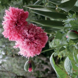
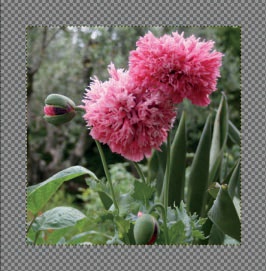
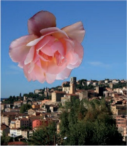
Figure 16-1 shows the Image: Image > Transform menu. All the entries on this menu act on the image as a whole, which means the transformation is applied to all layers in the image. We demonstrate these transformations on the image shown in Figure 16-2 by applying each transformation in the Image: Image > Transform menu to the original image.
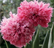
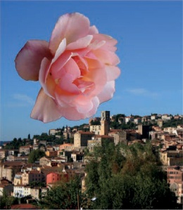
FLIP HORIZONTALLY produces the result shown in Figure 16-3. After the transformation, the flowers are a mirror image of the original. This transformation exchanges pixels symmetrically around the central vertical axis.
FLIP VERTICALLY exchanges pixels symmetrically around the central horizontal axis. The result appears in Figure 16-4.
ROTATE 90° CLOCKWISE does not involve symmetry around the main diagonal. The resulting image is not mirrored but is simply rotated 90°. See Figure 16-5.
ROTATE 90° COUNTER-CLOCKWISE is not a horizontal flip of the preceding rotation; the flowers are rotated from the original position in a counterclockwise direction. See Figure 16-6.
ROTATE 180° does not produce the same result as FLIP VERTICALLY; the flowers are not changed, simply rotated. See Figure 16-7.
GUILLOTINE is, in fact, named after the obsolete French execution device. The GIMP feature is quite handy—and much less dangerous.
Before using GUILLOTINE, place guides to delimit regions of the image, as shown in Figure 16-8.
When GUILLOTINE is selected, GIMP creates a separate Image window for each distinct rectangle delimited by the guides. In this example, nine windows are created, as shown in Figure 16-9. Figure 16-10 shows the central rectangle containing the flowers. This tool is sometimes used in web development to cut a large image into many components that are each associated with a different link. See also Slice.


The canvas of an image is the full visible area, which may extend beyond the area visible in the Image window, especially if the zoom factor is high. Conversely, the window may display areas outside the canvas, generally represented as a neutral color. Layers are often, but not necessarily, the same size as the canvas; layers can be smaller than the canvas, or regions of a layer can extend beyond the canvas. When a layer is larger than the canvas, the regions that extend beyond the canvas aren’t visible, but they still exist and can be moved into view.
Selecting Image: Image > Canvas Size brings up the dialog shown in Figure 16-11. We broke the chain that links the WIDTH and HEIGHT fields and reduced both values, so the new canvas is smaller than the original and has different proportions. In the preview, we moved the image so the flowers dominate. The new canvas boundaries are clearly shown in the preview. You could also increase the canvas size and press the CENTER button to place the image in the center of the new canvas.
If an image contains several layers, you can specify how the layers are handled via the RE-SIZE LAYERS drop-down menu at the bottom of the SET IMAGE CANVAS SIZE dialog, shown in Figure 16-12. The options are these:

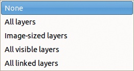
NONE: Leaves the layers unchanged.
ALL LAYERS: Resizes all layers to the canvas size.
IMAGE-SIZED LAYERS: Resizes only the layers that are the same size as the original canvas.
ALL VISIBLE LAYERS: Resizes only the layers whose visibility eye is checked.
ALL LINKED LAYERS: Resizes only the layers whose link icon is checked.
If you increase the size of the canvas, but do not resize any of the layers, then one or more areas will be created that contain no data. These areas are displayed as transparent, as shown in Figure 16-13. The empty area cannot be edited with any of the GIMP tools because no layer is present there. To make the empty space usable, enlarge at least one layer to the size of the canvas or select something other than NONE in the RESIZE LAYERS menu.
Select Image: Image > Fit Canvas to Layers to fit the canvas around all the existing layers. The edges are determined by whichever layer extends the farthest in a given direction. The canvas size can also be reduced if all layers are smaller than it is.
Image: Image > Fit Canvas to Selection is demonstrated in Figure 16-14, where we made a loose selection around some of the buildings, and in Figure 16-15, which shows the result.
Selecting Image: Image > Print Size brings up the dialog shown in Figure 16-16. This command doesn’t alter the image or compute any new pixel values. PRINT SIZE affects only how the image is printed; it only works with some printer software; and even when it does work, its parameters are overridden by those of the printer software. This command is useful as a means to compute the print size but not to specify it.
In the Set Image Print Resolution dialog, sets of values are linked together: If WIDTH is changed, the X RESOLUTION changes in proportion, and vice versa. Likewise, if HEIGHT is changed, the Y RESOLUTION changes. Moreover, if the chain beside the resolutions is not broken, all the values change when one value changes. Several different units are available for size (inches, millimeters, points, and picas, or even feet, yards, centimeters, and meters) and for resolution (pixels per inch, millimeter, point, pica, and others).


Selecting Image: Image > Scale Image, on the other hand, changes the entire image, sometimes dramatically. Its dialog, shown in Figure 16-17, is almost identical to the previous one. But a chain now appears beside the WIDTH and HEIGHT fields, which allows you to change the image proportions (see Figure 16-18). Note also that dimensions can be expressed as a percentage of the original size. The actual size in pixels is always displayed just below. And a new field, QUALITY, has a few options. Unless you’re working on a huge image or have a very old computer, always choose the best interpolation quality, which is the SINC (LANCZOS3) algorithm. When resizing an image, all its pixels must be computed anew using an interpolation algorithm. A poor algorithm causes significant deterioration in image quality.

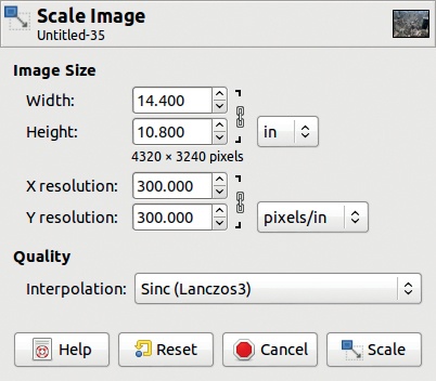

A good rule of thumb is to work on an image at the largest size possible and to scale it down only when you’re ready to use it.
When an image is resized, all its contents are retained, although a loss of quality can occur. When an image is cropped, on the other hand, some of the content is removed.
Image: Image > Crop to Selection appears to do exactly the same thing as FIT CANVAS TO SELECTION. Actually, however, FIT CANVAS TO SELECTION doesn’t remove any information from the image; it just hides certain areas, which you can reveal by moving the layer and thus changing which areas are hidden. On the other hand, CROP TO SELECTION removes part of the image, as the layers are cropped to the new canvas size. After using CROP TO SELECTION, the image size is reduced. You can see the current image size in the Image window’s status bar.
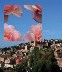
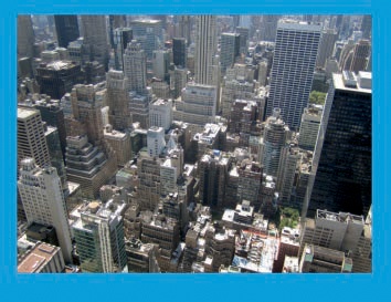
To demonstrate Image: Image > Autocrop Image, we added a frame to the example photograph, as shown in Figure 16-19. To do this, we added a transparent layer, built a rectangular selection around the photo, inverted the selection, and filled it with bright blue. Figure 16-20 shows the Layers dialog. AUTOCROP IMAGE crops all the layers of an image based on a frame in the current layer. The frame must be a homogeneous color. The result of our example appears in Figure 16-21.
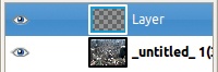

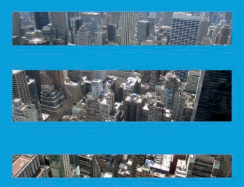
Image: Image > Zealous Crop works like AUTOCROP IMAGE, but it can remove central regions of an image in addition to an outer frame. Figure 16-22 shows an image prepared for a ZEALOUS CROP, and Figure 16-23 shows the result.
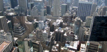
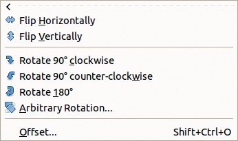

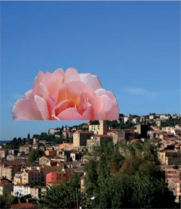
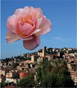
Figure 16-24 shows the Image: Layer > Transform menu. We demonstrate each of the tools in this menu on the image shown in Figure 16-25. The upper layer of this image contains only the rose, and the lower layer contains the city background.
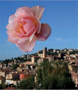
The first five entries on the Image: Layer > Transform menu are identical to those of the Image: Image > Transform menu, but they act on the current layer rather than on the entire image. The entries are demonstrated in Figure 16-26 to Figure 16-30.
The ARBITRARY ROTATION entry applies the Rotate tool, described in The Rotate Tool.
The OFFSET entry (which is also available via ![]() ) brings up the dialog shown in Figure 16-31. This command moves the contents within a layer without moving the layer relative to other layers in the image. The X and Y offset are set individually, in pixels or a variety of other units, including percentage. The OFFSET BY X/2, Y/2 button automatically sets these two fields to half the width and height of the layer, but you can adjust these values manually after pressing the button. EDGE BEHAVIOR is a set of radio buttons with the following three options:
) brings up the dialog shown in Figure 16-31. This command moves the contents within a layer without moving the layer relative to other layers in the image. The X and Y offset are set individually, in pixels or a variety of other units, including percentage. The OFFSET BY X/2, Y/2 button automatically sets these two fields to half the width and height of the layer, but you can adjust these values manually after pressing the button. EDGE BEHAVIOR is a set of radio buttons with the following three options:


WRAP AROUND: All pixels moved out of the layer from one side reenter it again from the other side. Figure 16-32 shows the result after pressing the OFFSET BY X/2, Y/2 button with this option selected.
FILL WITH BACKGROUND COLOR: The vacated areas of the layer are filled with the current background color. This option doesn’t work well on a layer with a transparent background and so is not shown.
MAKE TRANSPARENT: The vacated parts of the layer are filled with transparency. Figure 16-33 shows the result with a vertical offset of y/2 and no horizontal offset.