Understanding Interpolation Types
The object motion between adjacent keyframes can be controlled by altering the interpolation type. To understand interpolation types, think of a baseball player circling the bases. Although the shortest route between the bases is to run at right angles when viewed from above, base runners rarely run the bases in this manner. Instead, a runner circles around each base because his momentum carries him past the base. The resulting motion is rounded at each corner instead of a perfect square.
The same motion can be simulated by changing the interpolation type, which is found in the Timeline Settings dialog box. The selected interpolation type is then used for all new keys. The surface of each key has a marking that identifies the interpolation type. The available interpolation types in the Timeline Settings dialog box include the following:
| Smooth: Causes the interpolated motions between adjacent keys to be smooth to produce a gradual transition. | |
| Linear: Causes the interpolated motions between adjacent keys to be constant to produce a straight line. | |
| Ease In/Out: Gradually slows the motion as the key is approached and, likewise, gradually leaves the key as it moves to the next one. | |
| Ease In: Causes the interpolated motion between adjacent keys to be slowed as it approaches a new key. | |
| Ease Out: Causes the interpolated motion between adjacent keys to gradually increase as it moves away from a key. | |
| Step: Causes the position of the current key to remain until a new key is encountered and then the position of the new key is immediately jumped to. | |
| Noisy: Causes the interpolated motion between adjacent keys to be jittered like it is controlled by a noise function. |
The default interpolation type that is used for all new keys is set using the Default Interpolation setting in the Preferences dialog box. You can change this default to be any of the available interpolation types, but the default is the Smooth option.
Note
Some layers are limited in the interpolation types they can use. For example, Switch and Particle layers only have the Step and Cycle interpolation types available.
Once keys are added to the Timeline palette, you can change the interpolation type for the selected key or keys by right-clicking on the key and selecting the interpolation type from the pop-up menu. If multiple keys are selected, then the new interpolation type is used for all the selected keys.
When the Noisy interpolation type is selected from the pop-up menu, the Noisy Interpolation dialog box shown in Figure 17.9 appears. Using this dialog box, you can set the amplitude of the jittering noise. This amplitude value defines how far from center the object can move. The Scale value multiplies the effect.
Figure 17.9. Noisy Interpolation dialog box.

If you accidentally enable an interpolation type that you don’t want, such as the Noisy interpolation type, you can remove its effects by right-clicking the keys that have the noise applied and selecting a new interpolation type. Any keys with the Noisy interpolation type applied can be easily identified by looking at the pattern that is on the key.
To use the Step interpolation type to change a stoplight, follow these steps:
1. | Open the Stoplight.anme file from the Chapter 17 folder on the CD. This file includes a simple stoplight with red, yellow, and green lights. Each light is set to change color after twenty frames. The problem is that between frames 1 and 20, the red light slowly dims to gray while the yellow light slowly turns yellow and then dims to gray by frame 40, and the green light slowly becomes green at frame 40. This would not be a very effective stoplight, but we can fix it with the correct interpolation type. |
2. | Click the Settings button in the Timeline palette and enable the Fill Color and Selected Fill Color channels. Then close the Timeline Settings dialog box. This makes the keys for these channels visible in the Timeline palette. |
3. | |
4. | Click the Play button (Spacebar) and notice how each color stays the same until the frame where the key is located. Then it instantly changes to the new color, just as a stoplight should, as shown in Figure 17.10. |

Channel Cycling
The key right-click pop-up menu also includes an option to Cycle. When this interpolation method is used, the animated section that is cycled repeats indefinitely. Choosing this option opens the Cycle Interpolation dialog box shown in Figure 17.11. The Absolute option lets you specify a frame number (in the Value field), and the cycling section will run from the current key to the designated frame. The Relative option defines a section by counting backward from the current frame the value you specify.
Figure 17.11. Cycle Interpolation dialog box.

The cycling section in the Timeline palette is indicated by changing the key to an arrow and attaching a red line back to the cycled section, as shown in Figure 17.12.

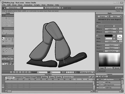
To use the Cycle interpolation method to repeat a set of walking legs, follow these steps:
1. | Open the Walking legs.anme file from the Chapter 17 folder on the CD. This file is the same file created in Chapter 26, “Creating and Binding Bones,” where a set of legs is controlled with some bones. The legs have been animated with keys that complete one walk cycle. |
2. | Select the left leg bone layer in the Layers palette and right-click on the last bone at frame 24. From the pop-up menu, select the Cycle option. In the Cycle Interpolation dialog box that appears, select the Absolute option with a Value of 1. This will create a cycle from frame 24 back to frame 1. |
3. | Repeat step 2 for the right leg bone. |
4. | Press the Play button (Spacebar) to see the resulting animation. The walk cycle works fine until it gets to the end of the frame range, where it shudders as the animation starts over. To fix this problem, hold down the Alt/Opt key and click the frame range at frame 69. This sets the frame range to repeat over exactly where the legs begin their cycle, resulting in a smooth repeating walk cycle, as shown in Figure 17.13. |