
Editing Elements Interactively
Revit provides a range of options to interactively edit elements in the model. The most obvious is to select elements to drag on the screen or use the blue control grips to extend walls, lines, shape faces, and region boundaries; however, you often need more precise ways of moving and copying objects. Let's look at some ways to do this.
Moving Elements
You can move elements in several ways, ranging from choosing traditional tools to using intelligent dimensions that appear on the fly when you select elements. Become familiar with each method and determine what is best for your workflow.
USING TEMPORARY DIMENSIONS
You have likely noticed by now that dimensions appear when elements are selected or newly modeled in Revit. These dimensions are called temporary dimensions and are there to inform you of the location of the elements relative to other elements in the model as well as to help you reposition them. Clicking the blue dimension value makes it an active and editable value. Type in a new value, and the selected element will move accordingly. Remember that when you are editing the position of an element via the dimensions, it will always be the selected element that moves. You can't change a dimension value if nothing is selected.
If a temporary dimension isn't referencing a meaningful element, you can choose a different reference by dragging the small blue square on the dimension's witness line to a new parallel reference, which will highlight when the mouse moves over them (Figure 3.6). For example, if you want to position a door opening at a specific dimension from a nearby wall, you will need to drag the grip of the temporary dimension that references the center of the door to the side of the opening. Then you can edit the value of the dimension as required. When you are dragging the grip of a temporary dimension, you can also use the Tab key on the keyboard to cycle through available snapping references near the mouse pointer.
FIGURE 3.6 Drag or click the blue grip to change the reference of the temporary dimension.

If you click a blue grip, it cycles to the next possible reference in the element. For example, clicking the grip of a dimension to a door or window cycles between the left and right openings and the center reference. The same applies to walls: try clicking the grip on the temporary dimension extending from a wall and see how the dimension cycles through the various references in the wall (interior face, centerline, exterior face). Note that when you drag a temporary dimension reference to a different position, the new reference is remembered when you return to the element for future editing.
You can also change the default behavior of temporary dimensions using the Temporary Dimension Properties dialog box shown in Figure 3.7 (on the Manage tab, click Additional Settings and then selecting Temporary Dimensions). Here you can specify how temporary dimensions will reference walls, doors, and windows independently.
FIGURE 3.7 The Temporary Dimension Properties dialog box lets you define default behaviors based on your modeling needs.

You can now modify the font size and transparency of temporary dimensions in the program options. To customize these values, click the Application menu and select Options. In the Options dialog box that opens, switch to the Graphics tab and locate the Temporary Dimension Text Appearance settings. Adjust the text size and transparency according to your needs.
If you have many elements selected at the same time or select an element within the proximity of a large number of other elements, temporary dimensions sometimes don't appear. Check the Options Bar for the Activate Dimensions button; clicking it will make the temporary dimensions appear in the view.
BEHAVIORS FOR MODIFY TOOLS
In Revit you have the option to activate the tools without any elements selected. If you choose this method, you must press the Enter key when the objects you intend to modify are selected.
You can also switch between any of the Modify panel tools while you have elements selected. For example, if you initially chose Mirror – Pick Axis and selected an element during the command, you can simply activate the Mirror – Draw Axis command without reselecting the elements.

USING THE MOVE TOOL
![]() Use the Move tool to relocate elements with more precision than by simply dragging them. The tool allows you to type in values or use temporary dimensions as helpers.
Use the Move tool to relocate elements with more precision than by simply dragging them. The tool allows you to type in values or use temporary dimensions as helpers.
Moving elements is a two-click process: first you define a start point, and then you click to define a destination. If you know you need to move something a specific distance, it doesn't matter where your two picks take place. All that matters is that the distance between the two clicks is the specified distance. Alternatively, you can type the desired value after picking the first point and guiding the mouse pointer in the desired direction of the move. This behavior is similar to the Move command in AutoCAD.
There are a few options on the Options Bar to be aware of when the Move command is active:
![]()
Constrain When this option is selected, it constrains movement to horizontal and vertical directions. Deselecting it allows you to move the elements freely as long as the element is not hosted. Hosted elements such as windows or doors always move in a constrained manner parallel to their host's axis.
Disjoin Hosted elements can't change hosts and move to another host without being explicitly disjoined from their original host. This option lets you disconnect inserts from their hosts and move them to new hosts. For example, if you need to move a door from one wall to another, select the door and activate the Move tool. Select the Disjoin option and move the door to another host. Similarly, you can use the Disjoin option to move one wall away from another without maintaining the join between the two elements.
Multiple The Multiple option is not active for the Move tool. This option is only available when you switch to the Copy tool.
NUDGING ELEMENTS
Nudging is a simple way to push things around quickly, as you would in software programs such as Microsoft Office. When elements are selected, you can use the arrow keys on the keyboard to move the elements horizontally or vertically in small increments. Each press of an arrow key nudges the element a specific distance based on your current zoom factor. The closer you zoom, the finer the nudge is. Note that your snap settings do not affect the nudging distances set by the zoom level.
MOVING WITH NEARBY ELEMENTS
A simpler way to constrain freestanding elements is to use the Moves With Nearby Elements option. This setting is designed to capture logical relationships between elements without establishing an explicit constraint. When furnishing a space, for example, you probably want to align the bed or dresser with an adjacent wall. If you change the design of the space, you want the furniture to follow the wall to the new location. For this purpose, select the furniture and then select Moves With Nearby Elements in the Options Bar, as shown in Figure 3.8.
FIGURE 3.8 Once an object is selected, it can be set to move with nearby elements.

By setting this option, you create an invisible relationship between the bed and the wall so that each time you move the wall, the bed moves with it. To clarify the difference between this approach and other constraint relationships, you could create a wall-hosted family, but that would limit your placement options and would subject instances to deletion if the host is deleted. You could align and constrain the family to its host, but too many explicit constraints will adversely affect model performance.
Copying Elements
![]() The Copy tool is another modifying tool that is nearly identical to the Move tool but makes a copy of the selected element at the location of the second pick. This tool doesn't copy anything to the clipboard; it copies an instance of an element or selection of elements in the same view. If you change views while using this tool, your selection is lost.
The Copy tool is another modifying tool that is nearly identical to the Move tool but makes a copy of the selected element at the location of the second pick. This tool doesn't copy anything to the clipboard; it copies an instance of an element or selection of elements in the same view. If you change views while using this tool, your selection is lost.
To activate this tool, either choose elements you want to copy and then select the Copy tool in the Modify tab in the ribbon, or activate the Copy tool first, select elements you want to copy, and then press the Enter key to start the copy process. Using the Options Bar, you can choose to make multiple copies in one transaction by selecting the Multiple option.
![]()
An alternative to the Copy tool is to use standard Windows accelerator keys to copy elements. To quickly copy a single element without the precision of the Copy tool, click and drag on an element while pressing the Ctrl key on your keyboard. This technique is useful for quickly populating a quantity of elements in a design without the required precision of the multiple picks of the Copy tool.
COPYING USING WORKSETS
If you are working in a model in which worksharing is enabled, be careful when performing any type of copying method. These methods include pasting from the clipboard, mirroring, and arraying, as well as using the Copy tool. Copied elements will always be placed on the active workset, not the workset of the original object. For example, if you are copying chairs that have been placed on the workset named Furniture but your active workset is Structure, the copied chairs will be assigned to the Structure workset.
Rotating and Mirroring Elements
![]() When refining or expanding your building design, you will likely find a frequent need to rotate or mirror one or more objects. Just as with moving or copying, Revit provides a few methods for these types of interactive operations. The quickest way to rotate elements in 90-degree increments is by pressing the spacebar on your keyboard. For more precision, you can use the Rotate tool to rotate elements to any specific angle you require.
When refining or expanding your building design, you will likely find a frequent need to rotate or mirror one or more objects. Just as with moving or copying, Revit provides a few methods for these types of interactive operations. The quickest way to rotate elements in 90-degree increments is by pressing the spacebar on your keyboard. For more precision, you can use the Rotate tool to rotate elements to any specific angle you require.
USING THE SPACEBAR
You can use the spacebar to rotate elements both at the time of placement and after an element has been placed. In addition to rotating an object through 90-degree increments, pressing the spacebar will locate any nearby diagonal references (walls, grids, or reference planes) as rotation candidates. This is a great timesaving command to become familiar with because you can forgo the necessity of using an additional tool such as Rotate And Mirror after placing an object. Here are a few examples:
Doors and Windows If you have a door with its swing in the wrong direction, select it and press the spacebar. You can cycle through all four possible orientations of the door using the spacebar. The same holds true for windows; however, many window families are built to only let you flip the window from inside to outside because many windows are symmetrical in elevation. If you are creating an asymmetrical window family, be sure to add flip controls to the window family during its creation. These controls allow the spacebar to work on hosted elements.
Walls If you select a wall, pressing the spacebar flips the element as if it were being mirrored about its length. Walls flip based on the wall's Location Line, which often isn't the centerline of the assembly. If you aren't sure which direction your wall is facing, select it and look for the flip-control arrows. These are always located on the exterior side of walls (Figure 3.9).
FIGURE 3.9 The flip arrow is another way to reorient an element. For walls, it is always found on the exterior side.

Freestanding Elements If you select a freestanding element, the spacebar rotates the element about the center reference planes defined in the family. Depending on how the family was built, the rotation origin may not make the most sense. If you decide to edit a family to change the location of the geometry relative to the center reference planes, be careful: when the family is loaded back into a project, all instances of the family will jump to a new location based on the change you made relative to the reference planes.
USING THE ROTATE TOOL
![]() To rotate an element, select it and click the Rotate tool. Remember, you can also activate the Rotate tool first, select one or more elements, and then press Enter to begin the operation. This is a two-click operation similar to the Move and Copy tools. Alternatively, you can enter numeric values for the desired rotation angle. Revit locates the geometric center of the selected elements and uses that as the default center of rotation; however, you will most likely want to designate a more meaningful center.
To rotate an element, select it and click the Rotate tool. Remember, you can also activate the Rotate tool first, select one or more elements, and then press Enter to begin the operation. This is a two-click operation similar to the Move and Copy tools. Alternatively, you can enter numeric values for the desired rotation angle. Revit locates the geometric center of the selected elements and uses that as the default center of rotation; however, you will most likely want to designate a more meaningful center.
To choose a new center of rotation, you have a couple of options. First, you can select the elements you want to rotate and drag the center icon to a new location before clicking to set the starting reference angle. Note that you might have to zoom out in order to find the center icon. Once the center is established, begin rotating the element using the temporary dimensions as a reference or by typing in the angle of rotation explicitly. The second option is to select elements you want to rotate and then use the Place option to locate the origin without dragging.
![]()
You'll notice that while moving the center of rotation, you lose the ability to pan and zoom the view. To overcome this, drag the center into the Project Browser and release the mouse button; then move the mouse pointer back into the view. The mouse pointer changes to a rotation icon, and you can freely zoom and pan to the desired location. The next click you make places the origin, and you can continue with the rotation operation. Note that you can also use keyboard snap shortcuts to refine the location of the center of rotation while dragging it. For example, type SE to snap to an explicit endpoint while dragging.
USING THE MIRROR TOOL
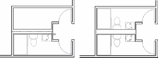
![]() The Mirror tool allows you to mirror elements across an axis in order to create a mirror image of an element or multiple elements. You can either pick an existing reference in the model with the Mirror – Pick Axis tool or draw the axis interactively using the Mirror – Draw Axis tool. In Figure 3.10, the centerline of the plumbing chase wall was picked as the axis for mirroring the plumbing fixtures.
The Mirror tool allows you to mirror elements across an axis in order to create a mirror image of an element or multiple elements. You can either pick an existing reference in the model with the Mirror – Pick Axis tool or draw the axis interactively using the Mirror – Draw Axis tool. In Figure 3.10, the centerline of the plumbing chase wall was picked as the axis for mirroring the plumbing fixtures.
FIGURE 3.10 The sink, toilet, and bath fixtures are mirrored about the centerline of the chase wall.
As with the other Modify tools you have seen so far, the Mirror tools have the option to create a copy of the selected elements or to simply mirror the selected elements to a new position. You can find the Copy option in the Options Bar after you activate either of the Mirror tools.
![]()
BE CAREFUL WHEN MIRRORING
The Mirror tools should be used carefully on any type of freestanding elements that may be asymmetrical in design. Revit does not restrict you from using the Mirror tools on any object; however, performing this operation to suit a design may distort a product component. For example, if an asymmetrical chair family was loaded into your model and you decide to mirror it to fit a space layout, the mirrored version of that chair may not be a viable product offered by the manufacturer. Remember that although an object can be scheduled, the schedule cannot determine if the object has been mirrored.
Arraying Elements
![]() An array allows you to copy instances of an element with equal spacing between the instances. Revit provides the option to create intelligent arrays that can be grouped and associated for further refinement as well as one-off, unassociated arrays. Like the other tools we've reviewed in the Modify tab of the ribbon, the array options are presented on the Options Bar.
An array allows you to copy instances of an element with equal spacing between the instances. Revit provides the option to create intelligent arrays that can be grouped and associated for further refinement as well as one-off, unassociated arrays. Like the other tools we've reviewed in the Modify tab of the ribbon, the array options are presented on the Options Bar.
![]()
You can create two types of arrays: linear and radial. Linear arrays are set as the default because they're the most common. As you would expect, a linear array creates a series of elements in a line. Each element in the array can be given a defined distance from the previous element (Move To 2nd option) or can be spaced equally based on a defined overall array length (Move To Last option). Figure 3.11 shows a linear array where the Move To 2nd option was selected in order to define a fixed distance between each instance in the array. Think of this type of array as additive and subtractive: if you change the number, the length of the array increases or decreases.
FIGURE 3.11 The Move To 2nd option is used in the Array tool to set a fixed distance between instances.
If you want to arrange elements in a fixed space and the exact spacing between elements is less important, use the Move To Last option. Figure 3.12 shows an array where the location of the last element in the array was picked and the elements were placed equally between the first and last elements in the array. With this option, the length is fixed and the array squeezes elements within that constraint as the number changes.
FIGURE 3.12 This array uses the Move To Last option and fills instances between the first and last instances.

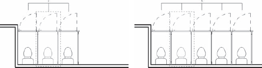
A radial array uses the same options as a linear array, but it revolves around a center point. The Move To 2nd and Move To Last options function as angles instead of distances in a radial array. You can specify the instance angle or overall array angle with two picks, or you can enter a specific value. With this type of array, elements autorotate so that each element faces the center of the array, as shown in Figure 3.13.
FIGURE 3.13 Elements will autorotate in a radial array.

The radial array is a little trickier than a linear array. Here is how to achieve the example shown in Figure 3.13:
- Before starting the radial array, draw a detail line to help locate the intended center of the array.
- Select the element and activate the Array tool from the Modify tab in the ribbon. Select the Radial option button, change Number to 6, and choose the Move To Last option.
- Drag the center of rotation off the element and to the endpoint of the detail line you drew in step 1.
- Click the mouse to define any starting point. An exact starting point is not important because you will be defining a complete circle in the next step.
- Do not click a second time; instead, go to the Options Bar, type 360 in the Angle option, and press Enter on the keyboard.
Enabling the Group And Associate option allows you to treat an array as a group that can be modified later to adjust the number and spacing of the array. If this option is unchecked, then the array is a one-off operation and you have no means of adjusting the array after it is created.
As shown in Figure 3.11 and Figure 3.12, when an element in a grouped array is selected, a control appears indicating the number of elements in the array. Editing that number changes the number of elements in the array. This tool comes in handy when you're creating certain families because the array number can be associated with a parameter or driven by a mathematical formula. See Chapter 15, “Family Editor,” for a detailed exercise.
GROUPING ARRAYS OF DATUM ELEMENTS
When developing a project for a multistory building, you may find the Array tool a quick and easy way to generate many levels and grid lines. We recommend not using the Group And Associate option when arraying datum elements. Maintaining grids and levels inside groups can cause problems with elements that refer to those data.
Scaling Elements
The Scale tool lets you scale certain lines and graphic elements in 2D that are appropriate to be scaled, such as imported raster images and 2D line shapes. While not an obvious option, the Scale tool can be used in Sketch mode for any type of sketch-based element in a project or for solid and void geometry sketches in the Family Editor.
Keep in mind that you are working with a model made out of real-world objects, not abstract primitive forms. You cannot scale most elements in Revit because it's not practical or meaningful and may cause dangerous errors in scheduling and dimensions. For example, you can't scale the size of a door, wall, or sink because they represent real assemblies and scaling them would mean resizing all their components. This would lead to impractical results, such as a sink being displayed as a fraction of its actual manufactured size.
Aligning Elements
![]() If you've been using Revit for any amount of time, you have likely discovered the power of the Align tool. It has the ability to supplant the need to use many of the tools we've already discussed. The Align tool lets you line elements up in an efficient way that works on almost all types of objects.
If you've been using Revit for any amount of time, you have likely discovered the power of the Align tool. It has the ability to supplant the need to use many of the tools we've already discussed. The Align tool lets you line elements up in an efficient way that works on almost all types of objects.
With this tool, you explicitly align references from one element to another regardless of the type of either object. For example, you can align windows in a façade so their centers or openings are all in alignment. To use the Align tool, activate it from the Modify tab in the ribbon and first select the target reference—a reference to which you want to align another element. Next, select what you want to align to that reference—the part or side of the element whose position needs to be modified. The second element picked is the one that always moves into alignment. This selection sequence is the opposite of the other editing tools we've discussed so far, so remember: destination first, then the element to be aligned.
As soon as you make your second pick and the aligned element is moved, a lock icon appears allowing you to constrain the alignment. If you click the icon, thereby constraining the alignment, the alignment is preserved if either element moves. Figure 3.14 illustrates the use of the Align tool to align multiple windows in an elevation view using the Multiple Alignment option on the Options Bar.
FIGURE 3.14 You can use the Align tool for lining up edges of windows in a façade.

The Align tool also works within model patterns such as brick or stone on surfaces of model objects. Select a line on an object such as the edge of a wall, and then select a line in the surface pattern. Use the Tab key if you cannot get surface patterns selected with the first mouse click. Note that the Align tool will also rotate elements in the process of aligning them to objects which are not parallel. This is a real time-saver compared to moving and rotating.
Trimming or Extending Lines and Walls
![]() You can trim and extend lines and walls to one another using the Trim/Extend tools on the Modify tab of the ribbon. In older versions of Revit, this function was assigned to a single button with three options in the Options Bar. In the latest version, there are three separate tools in the ribbon: Trim/Extend To Corner, Trim/Extend Single Element, and Trim/Extend Multiple Elements. With the Trim/Extend tools, you first activate the tool and then operate on elements in the model, selecting two lines or walls that need to meet in a corner or as a T intersection.
You can trim and extend lines and walls to one another using the Trim/Extend tools on the Modify tab of the ribbon. In older versions of Revit, this function was assigned to a single button with three options in the Options Bar. In the latest version, there are three separate tools in the ribbon: Trim/Extend To Corner, Trim/Extend Single Element, and Trim/Extend Multiple Elements. With the Trim/Extend tools, you first activate the tool and then operate on elements in the model, selecting two lines or walls that need to meet in a corner or as a T intersection.
The Trim/Extend tools are used frequently for editing sketches of floors and roofs because it's easy to end up with overlapping lines that need to be trimmed to form a closed loop. Keep in mind that with the Trim/Extend tools, you are selecting pairs of elements to remain, not to be removed. While the Single Element and Multiple Elements tools are similar to the Extend command in AutoCAD, the behavior of the Trim/Extend To Corner tool in Revit is more like that of the Chamfer or Fillet commands, rather than its Trim command.
The Trim/Extend tools for extending a single element or multiple elements function in a slightly different way than Trim/Extend To Corner. To extend a wall or line, first select a target reference; then select the element you want to extend to that target (Figure 3.15). Using the Multiple Elements tool, you first select the target reference; then each subsequent pick extends the selected element to the target reference.
FIGURE 3.15 Extend walls to references by picking the target (1), then the wall to extend (2).

USE TRIM/EXTEND ON LINE-BASED COMPONENTS
You can use the Trim/Extend tools on line-based families that are either model or detail components. Try this using a line-based detail component for batt insulation or gypsum wallboard. The Trim/Extend tools will help make your detailing process much more efficient and fun!
Splitting Lines and Walls
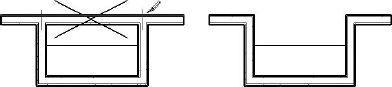
The Split tool operates on walls and lines and lets you divide an element into two pieces. To cut an element, activate the Split tool from the Modify tab in the ribbon and place the mouse pointer over the edge of a wall or line. Before you click, you'll see a preview of the split line. The split line will automatically snap to any adjoining geometry.
The Options Bar displays a nice feature called Delete Inner Segment that removes the need to use the Trim tool after a splitting operation. In Figure 3.16, you need to remove the middle section of a wall and end up with a clean set of wall joins. Using the Split tool with the Delete Inner Segment option checked, you can accomplish this with two clicks and get a clean condition without having to return with the Trim command.
FIGURE 3.16 Using the Split tool with the Delete Inner Segment option checked
SPLIT WITH GAP
The Split With Gap tool allows you to specify a gap distance and pick a single point on a wall. Although the wall is divided into two separate segments, the gap distance is maintained with an automatic constraint. To use Split With Gap, follow these steps:
- Go to the Modify tab and from the Modify panel, select Split With Gap.
- Specify the Joint Gap distance in the Options Bar. Note that this distance can only be set between 1/16″ [1.6 mm] and 1′-0″ [304.8 mm].
- Move the mouse pointer over a wall and click to place the gap.
Once you have successfully split a wall with a gap, select the wall and notice the constraints (locks) on the gap and between the two parallel wall segments. Try to drag either of the wall ends separated by the gap and you will see the gap distance is maintained. Try to move the wall in a direction perpendicular to the wall segments and you will notice the two wall segments remain aligned.
If you'd like to rejoin walls that have been split with a gap, follow these steps:
- Select a wall split with a defined gap.
- Click the constraint icon in the gap to unlock the dimension constraint.
- Right-click the end grip of one wall segment and select Allow Join.
- Select the other wall and repeat step 3.
- Drag the wall end grip of one wall segment to the end of the other segment. The walls should join.
Note that on walls with smaller gaps, the segments may automatically join as soon as you select Allow Join; however, rejoined segments may not form a single segment. If you have trouble joining two parallel wall segments into one, try to drag one of the wall ends away from the other and release the mouse button; then drag the segment back to the other end.
Offsetting Lines and Walls
![]() Offset is similar to the Move and Copy tools in that it moves and makes a copy of an element by offsetting it parallel to an edge you select. You can find the Offset tool in the Modify tab of the ribbon. You can also specify an offset distance as an option in the Options Bar when you are sketching lines or walls.
Offset is similar to the Move and Copy tools in that it moves and makes a copy of an element by offsetting it parallel to an edge you select. You can find the Offset tool in the Modify tab of the ribbon. You can also specify an offset distance as an option in the Options Bar when you are sketching lines or walls.
This tool is especially useful in the Family Editor when you're making shapes that have a consistent thickness in profile, such as extruded steel shapes. The Offset tool has a Copy option available in the Options Bar that determines whether the offsetting operation generates a copy of the selected elements or simply moves them.
Remember that you can Tab-select a chain of elements and offset them in one click, as shown in Figure 3.17.
FIGURE 3.17 Use Offset with Tab-select to copy a chain of elements

Keeping Elements from Moving
In some cases, you may want to make sure some elements in the model never move. An example of this is when you work on a renovation to an existing building. For obvious reasons, you would not like to move walls in the model that are already built in reality. Other examples include imported drawings, grids, levels, and exterior walls. Revit provides two ways to deal with this and lock certain elements, thus preventing them from moving.
PINNING ELEMENTS
You can restrict an element's ability to move by pinning it with the Pin tool. Use this tool to lock down critical elements that need to remain fixed for long periods of time. This is an important tool to use on imported CAD files, because it's easy to accidentally select an import and drag it or move it. This kind of accidental modification can lead to coordination problems, even in a BIM environment. Use pins to lock down gridlines as well, because you certainly don't want those to move accidentally either.
This tool is located in the Modify panel of the Modify tab in the ribbon. Select one or more elements for which you want to prevent movement and click the Pin tool. If you try to move the element, nothing will happen—you won't even get a preview of a potential move. To unpin an element, select it and click the Unpin icon, which is also located in the Modify panel. You can also unpin an element by clicking the pin icon that appears near a pinned element when it is selected.
DELETING PINNED ELEMENTS
Pinned elements can be deleted. This unfortunately is misunderstood by users who believe that a pinned element is safe from deletion. Revit will give you a warning after a pinned element is deleted, so pay close attention to these types of alerts.

CONSTRAINTS
Constraints aren't as rigid as the Pin tool, but they do allow you to create dimensional rules in the model so that elements remain fixed relative to other elements. You can create a constraint using dimensions or alignments and then click the lock icon that appears upon creation of a dimension or completion of an alignment operation.
A simple example of using constraints is maintaining a fixed distance between a door and a side wall. If the wall moves, the door will also move. If you try to move the door, Revit will not let you move it. Look at Figure 3.18; the door has been constrained to remain 4″ from the wall face.
FIGURE 3.18 A door constrained to a wall can't be moved independently of the wall.

This type of constraint is accomplished by placing a dimension string between the side of the door and the face of the wall and then clicking the lock icon on the dimension. Note that the dimension can be deleted while preserving the constraint. If you delete a constrained dimension, an alert will appear giving you the option to unconstrain the elements or simply delete the dimension while maintaining the constraint (Figure 3.19). Note that you can determine where constraints were by creating new dimensions; constrained relationships will still display with the lock icon. You can also view these relationships when a constrained element is selected. Simply hover the mouse pointer near the constraint icon and you will see the dimension constraint represented as a dashed dimension string.
FIGURE 3.19 Deleting a constrained dimension generates an alert.
