
Creating Railings
We consider in-the-box techniques to mean using the functionality in interesting and useful ways and leveraging intended functionality. But keep in mind that the metadata may or may not remain associated with the category of element that you're creating. For example, you can use the Railing tool to create railings, but you can also use it to distribute repetitive elements along a path that may not be railings at all—something we'll discuss later in this chapter. As a result, your schedules need to be watched carefully so that certain elements are properly counted and unwanted elements are ignored.
Understanding the Revit Railing Tool
Using a 3D pattern to represent geometry is not a new idea in Revit. We use pattern files to represent ceiling tiles, masonry patterns in walls, and other host elements. Using 3D patterns is a great way to go easy on your computer as well. And there are a couple of places where using model patterns is useful for creating specific types of railings.
Let's begin with an exercise. Many modern railings use a metal mesh as a railing panel infill. Creating these infill panels can be simple. This technique is also great when the wire mesh panels are curved (Figure 16.11).
FIGURE 16.11 Patterns representing wire mesh

The technique can be accomplished in just a few steps:
- You'll need a piece of geometry to represent the “zone” of the mesh. This can be easily created in the Family Editor as a profile family (Application
 New Family Profile.rfa). In this case, the profile is a box 1″ [25 mm] wide by 2′-6″ [800 mm] high with an insertion point at the upper-left corner. Take care to place the insertion point in an obvious location (Figure 16.12). This is important to keep the top of the profile properly associated with the top handrail when used with stairs.
FIGURE 16.12 Wire mesh profile

- Save the family as Wire_Mesh.rfa and load into a default project. For this exercise, let's start with a simple railing of Railing – Handrail Rectangular. Duplicate the rail family by right-clicking it in the Project Browser and choosing Duplicate from the context menu. Rename it to Railing – Wire Mesh.
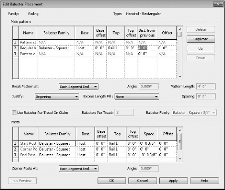
- Right-click the railing you just renamed again and choose Edit from the context menu. Select the Edit button next to Baluster Placement and in the Main Pattern portion of the dialog box, change the baluster placement from 0′-4″ to 4′-0″. This will give you plenty of space between the balusters and make room for the wire mesh (Figure 16.13).
FIGURE 16.13 Making room for the wire mesh
- Now let's edit the Rail Structure from the Type Properties dialog box. Currently, there is one line in this dialog box. Duplicate the existing handrail and change the elevation of the new rail to 4″. Then click the Insert button to add another region and associate it with the wire mesh profile that you previously created (Figure 16.14).
 Still in the Edit Rails dialog box, we want to create a new material for the mesh. In the Material column, select the <By Category> button for the Wire Mesh material. This pulls up the Materials dialog box. Create a new material by duplicating any material already selected. Name it Wire Mesh and click OK.
FIGURE 16.14 Edit Rails dialog box

On the Graphics tab, choose the Surface Pattern icon ![]() . Select the Model radio button at the bottom of the Fill Patterns dialog box and click New. Name this new pattern Wire Mesh as well. Use a 2″ × 2″ crosshatch pattern at 45 degrees. Finally, set the Transparency value for shading to 100% and click OK. Figure 16.15 shows the final settings for the Materials and Fill Patterns dialog boxes.
. Select the Model radio button at the bottom of the Fill Patterns dialog box and click New. Name this new pattern Wire Mesh as well. Use a 2″ × 2″ crosshatch pattern at 45 degrees. Finally, set the Transparency value for shading to 100% and click OK. Figure 16.15 shows the final settings for the Materials and Fill Patterns dialog boxes.
FIGURE 16.15 Wire mesh pattern settings

When you finish, a portion of your railing should look like Figure 16.16.
FIGURE 16.16 Finished wire mesh railing

Now create some stairs (any configuration is fine). When you're finished, swap out the default railing on your stairs by selecting the railing, then choosing the Mesh Rail from the Type Selector. Now, you can see your new railing in action (Figure 16.17).
FIGURE 16.17 Mesh railing for stairs
This technique is great for indicating fences with vertical or horizontal battens (rather than building them out of actual geometry). This file is also available for download from the book's companion web page (www.sybex.com/go/masteringrevit2012) in the Chapter 16 folder; look for the Wire Mesh Railing and Stair.rvt file.
RAILINGS AS REPETITIVE SYSTEM
Currently, Revit doesn't have a specific tool to allow components to be quickly and easily distributed along a user-defined path. In some cases you could use line-based families, but these don't work in curved conditions. In the meantime, we think you should consider using the Railing tool to distribute elements along paths for a variety of uses besides just for railings.
When using railing functionality outside of a railing to distribute elements along paths, keep in mind these three rules:
- You'll likely want to nest your family into a baluster family template (rather than creating it directly as a baluster). This is because the existing parameters within the baluster family can cause your geometry to fly apart if it needs to move up and down as a single element.
- Don't expect your nested element to schedule or tag. If you need the elements to schedule or tag individually, you probably want to place them individually (or use another technique like a line-based family).
- Don't share parameters of nested families in an attempt to schedule. Your element won't schedule properly — it'll break.
In some cases, you'll want the railing family to have associated profiles, like the shading device in Figure 16.18. The railing profiles are used to create the shading fins, and the balusters are the support elements.
FIGURE 16.18 Railing as shading device

But railings don't have to contain handrail profiles. Follow these steps to delete a railing profile:
- In the Edit Baluster Placement dialog box, set the Top value of the railing to Host.
- Give the baluster a positive Top Offset value. This activates the delete button on the right.
- Delete the railing profile. This hosts the baluster by the host rather than the railing profile. Picking any of the balusters will allow you to edit the sketch. But the profile of the railing won't be seen until you select any one of the elements and edit their associated sketch.
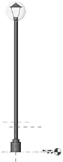
Using railings to quickly and evenly distribute components along a path is great during design and allows for quick iteration. Outdoor elements are particularly appropriate for distributed placement, like a lamppost (Figure 16.19). In this example, a lamppost has been nested into a baluster family.
FIGURE 16.19 Lamppost nested into a baluster family
Once this lamppost has been nested, you'll be able to create a custom “railing” with the lamp designated as the “baluster.” This will allow you to quickly and easily distribute lampposts along a sketch at specific intervals that can be modified as a parameter. So for example, if the lamppost was originally distributed on 60′ [18 m] centers, you could very quickly redefine it to occur on 40′ [12 m] intervals (Figure 16.20).
You can use this for any repetitive elements that must be placed on center and evenly distributed along a path. Other uses might include pipe bollards and outdoor planting.
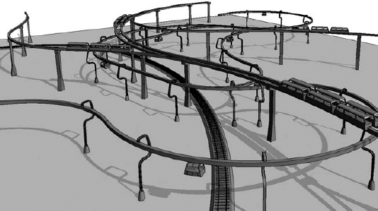
Even a design pass at light rail tracks (including railcars) can be distributed along paths (Figure 16.21). In this case, the rail sleepers are balusters and profiles are used to create the rails and the rail bed. The monorails are easy, too. The vertical supports and railcars are balusters, and the suspended track is the rail profile. This file can be downloaded from the Chapter 16 folder on the book's companion web page. Look for the Monorail and Railway Railing.rvt file.
FIGURE 16.20 Lampposts distributed along a path as a baluster family

FIGURE 16.21 Transportation components as railings
Railings Outside the Box
Railings outside of the box are meant to be railing-like, geometrically speaking, but they're not created with the Railing tool. Usually this occurs when the railing is a small, unique, or highly repetitive element.
Generally speaking, maintaining order in Revit projects is often about managing repetitive relationships. These repetitive elements may be managed by creating family components, groups, and even separate Revit files. For railings, there is an obvious choice: create the railing, then create a group of the finished railing and then copy that group throughout your finished project.
It's often faster to manage and update hundreds of components than it is to update hundreds of groups. The railing may also be prefabricated and installed onsite as a single component, perhaps filed under the Revit category of Specialty Equipment. If you decide to use the category of Specialty Equipment, keep in mind that the category won't cut in sections; you'll always see a projected elevation. So, choose a category (like Generic Model) if you need to see the family cut in section.
What kind of highly repetitive railing conditions are we referring to? Sport stadiums, theaters, hotel balconies (Figure 16.22), apartment buildings, and so on all have railing conditions that are highly repetitive. Railings modeled as a singular component in the Family Editor are perfect for these kinds of situations where only a few family components can cover hundreds of conditions.
FIGURE 16.22 Repeated railings on a hotel

CUSTOM HANDRAIL JOINS
Custom handrail joins are known to frustrate many a Revit user. Following the logic of custom rails, if modeled in the Family Editor and associated with the railing, it's a challenge that can often be easily overcome. What's important is that you'll need some context to model your custom condition. So model the context of what you need as a starting point:
- Open a default template and sketch a stair with dimensions shown so that there's really no reason to have a railing between the two runs, but the railing should still be continuous (Figure 16.23). Note that there is only 6″ separating each run.
- Associate the Handrail – Pipe railing with the stairs and the problem is obvious: how to properly model the join between the railings (Figure 16.24)?
FIGURE 16.23 Stair sketch in plan
FIGURE 16.24 Example of an unjoined handrail

- In order to model the join between handrails, it'll be helpful to have some context. Activate a section box around the desired portion of the handrail in a 3D view. Then export this 3D section to CAD by selecting Application Export CAD Formats and choosing DWG Files. The resulting export should look like Figure 16.25.
FIGURE 16.25 Exporting the railing context

- Since the handrail join will be part of your baluster, duplicate the default round baluster family by right-clicking it in the Project Browser. Rename the new family Baluster - Round with Join.rfa. Open the new baluster family by right-clicking it again and choosing Edit from the context menu, and import this 3D context into your duplicate baluster family. Before you start to model the connections, it may helpful to create some reference planes (Figure 16.26).
FIGURE 16.26 Use reference planes in context with the imported railing geometry.

If modeling in a nonstandard 3D view is a challenge, try to model what you're creating in a standard 3D view and then rotate your component into place. You'll still be able to edit it afterward. In this case we've modeled half the join and then mirrored the other half (Figure 16.27) in context with the portion of the exported handrail.
FIGURE 16.27 Modeled handrail join in context with railing export
- Once you're done modeling the connection, just delete the exported background. Save your file.
- Back in the project environment, you'll want to delete the portions of the handrail sketch that are shown in Figure 16.28 as highlighted in blue. Keep in mind that the lower portion of the railing will be completed as a separate, hosted sketch. You won't need to model the railing connecting the upper and lower runs. Finally, the lower, hosted railing run will be the default Type Baluster – Round, not the custom baluster that we are making.
FIGURE 16.28 Deleting the blue portions of the inner handrail sketch
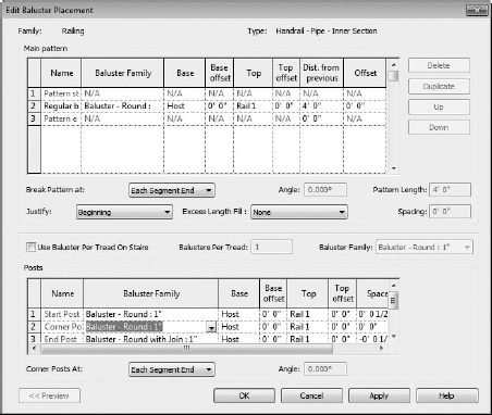
- Duplicate the remaining portion of the inner handrail and rename it to Handrail – Pipe – Inner Section. This will differentiate it from the default Handrail – Pipe. Now you can edit the value of the end post to the baluster family in the Edit Baluster Placement dialog box and add the one we've just created (Figure 16.29).
FIGURE 16.29 Edit the end post to associate with the handrail join.
- Through a system of careful measurements (as well as a bit of trial and error), you'll want to elevate, rotate, and finally nudge the handrail join portion of the baluster family until it's in the correct position with regard to the upper and lower handrail runs (keeping in mind that the lower run is a separate sketch). Just remember to reload the baluster family into the stair project to make sure that your adjustments are correct.


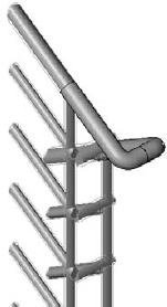
After a few moments, you'll end up with a custom connection, as shown in Figure 16.30. The great thing about this technique is that it works with multistory stair conditions. You can download the completed project in the Chapter 16 folder at the book's web page; the file is named Custom Handrail Join Project.rvt.
FIGURE 16.30 Completed handrail join

THREE-RUN STAIRS
Revit makes it challenging to create a three-run stair. You can't have overlapping sketches when using the Railing or Stairs tool, so you're obviously going to have to create two separate sketches. This is where most people run into problems: they divide the sketch at one of the landings.
A better technique involves breaking the stair and railing in the middle of the second run, not at the landing. Here's how:
- Open a new project using the default template. Then open your South elevation and create a new Level 3, 10′ [3 m] above Level 2, as shown in Figure 16.31.

- Return to Level 1 to start your stair sketch with a stair from the first level to Level 3. You'll notice that the moment the sketch starts, you're expected to create 18 risers to complete half of the three-run stair—which means that each run will be 12 risers (36 total risers divided by three runs). Instead of making all the runs equal, sketch your first run with 12 risers, then a landing and another 6 risers (Figure 16.32).
FIGURE 16.32 Half of the three-run stair

- Next, mirror the stair at the end of the second run. Change the direction of the second run in the plan view by clicking the directional arrow at the base of the stairs. This allows the landings to meet correctly.
- Modify the instance properties of the stair to start at Level 2 and finish at Level 3, as shown in Figure 16.33. You'll also notice that there's an “extra” tread overlapping the landing. Not to worry—we'll fix that in a moment.
FIGURE 16.33 Changing the properties of the mirrored stair

Go to the default 3D view and you'll notice that the second run doesn't meet the first run properly (Figure 16.34). That's because the stair you just mirrored starts with a riser (which you don't need).
FIGURE 16.34 Initially the stairs don't meet properly.

- Select the stair, then duplicate the stair in the Stairs Properties dialog box. You need to change the type properties of the second run, and to do this, you need to create a new type. Otherwise you would inadvertently modify both runs of stairs.
- Once you've duplicated the stair type, just allow the default naming convention (7″ [175 mm] max riser 11″ [300 mm] tread 2). Now, change the Extend Below Base value to −1′-6″ [800 mm] shown in Figure 16.35 and deselect the Begin With Riser option (not shown in the figure).
FIGURE 16.35 Completed stair connection

- Click OK. You'll be given a warning that the actual and desired numbers of risers are different. Ignore the warning for now and return to Level 2 and edit the sketch of the second stair. You'll notice that you need another tread to complete the stair.
- With the run still selected, choose Edit Sketch from the Modify Stairs context menu. Here, press and drag the run line of the lower run (the shorter run) to add an additional tread. Once this is done, select all the boundary lines, treads, and run lines within the sketch (basically everything). Move the entire sketch over so that the treads between the end of the first stair and the beginning of the second stair don't overlap. Finish the sketch. This will complete the connection between the first and second stair (Figure 16.35).
- With the stair completed, you now need to modify the railing to match. To do this, start by duplicating the type properties of the upper railing so there are two types similar to what we did with the stairs. Next, with the rail still selected, open the Type Properties dialog box and then click to edit the Baluster Placement. Here you'll need to modify a few of the type properties of the railing. Doing so will help set the railing types so they align properly in the center of the run without looking like they have started over.
- Set the Space value of End Post to 0″.
- Set the Start Post value of the upper railing to None.
- Set the Justify value for the Baluster Placement of the lower railing to End and the same value for the upper railing to Beginning.
Click OK to exit all the dialog boxes and you'll get the result shown in Figure 16.36.
FIGURE 16.36 Adjusting the type properties of the upper and lower railings

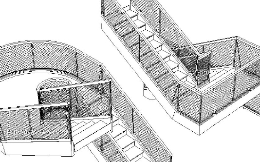
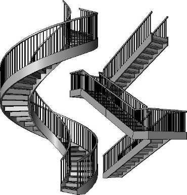
You can use this same process to create a spiral stair that is continuous and would otherwise overlap in Sketch mode (Figure 16.37). You can download the stairs in this example in the Chapter 16 folder on the book's web page; the file named Three Run Stair.rvt.
FIGURE 16.37 Continuous three-run straight and spiral stairs with railings
CURTAIN WALL OR GLASS RAILINGS
The most challenging of railings often require exceptions to the rules and the ability to manually locate balusters or panels that are not part of the routine railing definition. If you tried to define each of these exceptions as a different railing type, your project would be overflowing with railing types. The best solution for these types of railings is to diverge from the Railing tool and use the Curtain Wall tool.
By using the Curtain Wall tool, you'll be able to create railings by modeling the balusters and panels inside the Curtain Panel family template (Figure 16.38). Another nice feature about this technique is that the railing can be used as a space boundary, since Revit thinks it's a wall. That makes this perfect for mezzanine conditions that require room or space calculations—certainly more efficient than creating redundant room separation lines!
FIGURE 16.38 Curtain panel as a railing

Start by creating a single panel using the Curtain Panel template. The family may contain not only the panel for the railing, but also the balusters. Once you load this panel into your project, you can create curtain walls with predefined panel widths (Figure 16.39).
FIGURE 16.39 Curtain panel railing with custom baluster locations

Since curtain panels allow you to unpin predefined grids (as well as create other grid locations), you'll be able to quickly and easily make exceptions to the rules that you previously defined (Figure 16.40) and create several unique baluster locations specific to the installation.
FIGURE 16.40 Adjusted baluster locations

When you're creating railings as curtain walls, be sure to filter your schedules accordingly. If you want to download this example project, it's in the Chapter 16 folder on the book's companion web page, and is named Curtain Wall Railing.rvt.
These in- and out-of-the-box techniques should give you some great ideas for making custom railings faster and more interesting than you could ever have imagined.