
Revit for the Builder
Now that we have reviewed some basic functionality a design team might use in the construction phase, let's take a look at how a builder (contractor, subcontractor, or construction manager) uses Revit in the industry today.
Revit is often referred to as a design application; however, contractors are using Revit more frequently as both a model authoring and project analysis tool. Although builders use Revit to obtain different results than design professionals, many of the processes and functions are the same; they are merely applied in unique ways.
A builder might use Revit in one of several scenarios. Likely to be the most popular situation is the case in which builders will utilize Revit to construct their own virtual model of a project based on 2D drawings they receive from design teams. While this book encourages open sharing of 3D intelligent design data, the fact remains that many projects still share flattened plans, sections, and elevations for the construction phase.
ABOUT THE CONTRIBUTING AUTHORS: LAURA HANDLER, MIKE WHALEY, AND JOSH LOWE
Laura Handler oversees Tocci's virtual design and construction (VDC) process using BIM. In this key position, Handler manages the VDC team, including modeling, coordination, and optimization for all of Tocci's projects. She advances Tocci's use of VDC through research and development efforts. Apart from her duties at Tocci, Handler is active in the industry. She serves on the leadership committee of the BIMForum as a Leader at Large and participates actively in local organizations, including the Boston Revit Users Group, Boston Society of Architects BIM and IPD Committees, and the Associated General Contractors of Massachusetts. Handler presents frequently, locally and nationally, on VDC, IPD, and Tocci's use of this groundbreaking process. Her blog, http://bimx.blogspot.com, is widely regarded as one of the best sources of information regarding VDC and BIM. She was selected as one of the Building Design+Construction 40 Under 40 in 2009.
Mike Whaley is a graduate of the University of Wisconsin–Milwaukee. During the first 26 years of his career he worked as an architect; his professional focus was on project management of corporate, healthcare and municipal facilities. In 2005, Mike joined the J. H. Findorff & Son team, where he serves as director of preconstruction services. His role is to lead the early collaboration and integration between owner, designer, and contractor. Mike's technology initiatives have spearheaded Findorff to be an industry leader in the use of BIM and construction visualization software. This advance in preconstruction has improved collaboration, project savings, and project understanding, while demonstrating increased efficiency in the field. In addition to his BIM initiative, Mike was instrumental in the implementation of the first full three-part IPD project for Findorff.
Josh Lowe is a graduate of the University of Wisconsin–Milwaukee, where he received a bachelor of science in architectural studies and a certificate in urban planning. In 2004, Josh joined the J. H. Findorff & Son team, where he is currently a construction visualization and integration specialist. He is responsible for integrating trades during construction as well as promoting lean construction by leveraging the power of BIM in the field to increase productivity. In addition to the utilization of BIM models for projects, Josh is involved in the research and development of new BIM applications.
Another interesting use case is that of a contractor using Revit in conjunction with architects and engineers in an integrated project delivery (IPD) environment. In this case, the perceived risks of sharing complete model data are mitigated by the IPD contractual requirements. Design, engineering, and construction teams work together to ensure the ultimate success of the project. This process requires adequate planning and development of a robust BIM execution plan.
It is important to note that construction managers may only need to support the coordination of data by other builders or provide guidance in construction phasing, staging, or cost control. Although Revit can provide much of this functionality, many other powerful tools are available in the marketplace today. Programs from Autodesk such as Navisworks Manage and others such as Vico Office Suite, Synchro Professional, Solibri Model Checker, and Beck DProfiler are developing increased interoperability with Revit. For a more complete overview on the use of these tools, please read Brad Hardin's BIM and Construction Management (Wiley, 2009).
In the following case study, contributed by Josh Lowe and Mike Whaley of J. H. Findorff & Son, Inc., you will see that Findorff finds ways to use Revit to convert 2D design data and to generate working documents for their self-performed construction tasks. It covers BIM uses in preconstruction planning and in the construction phase by a contractor implementing Revit for the sake of their own productivity. Whether you are an architect, engineer, or builder, we hope you will find this case study informative and inspirational.
![]() Real World Scenario: CASE STUDY: J. H. FINDORFF AND SON, INC.
Real World Scenario: CASE STUDY: J. H. FINDORFF AND SON, INC.
Established in 1890, J. H. Findorff and Son, Inc., is a southern Wisconsin general contractor and construction management company with offices in Madison and Milwaukee. While employing an average of 600 construction professionals, they complete more than $300 million in construction annually. Findorff self-performs concrete, masonry, carpentry, steel erection, and drywall with their own teams. Their primary markets include healthcare, education (K–12), higher education (two-year and four-year), and a mixture of other commercial projects.
USING REVIT FOR PRECONSTRUCTION PLANNING
Using an intelligent 3D model to plan construction phase activities has several advantages over traditional approaches. Plans and uninformed spreadsheets not only take longer to produce but expose the opportunity for errors and misinterpretation. A model-based approach can support such activities as creating virtual mockups, planning for site safety, and work staging. Contractors can also use Revit in ways similar to that of an architect, as demonstrated in other chapters of this book.
One of the very first applications of Revit for Findorff was realizing the visualization capabilities of 3D images. On a major hospital project that involved multiple tower cranes, an early Revit model was used to demonstrate to the Med-Flight helicopter team how the tower cranes would look as the helicopters approached the hospital during construction. This involved modeling the existing hospital and site as simple massing elements in one overall model with the helicopter landing pads. Combined with models of the tower cranes (including their swing zones as shown here), this model allowed multiple flight path approaches to the hospital to be simulated.
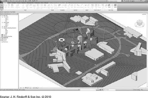
The model was then used to produce a series of animations that were presented to the hospital staff and flight crews. This mockup allowed construction to proceed with the confidence of the hospital administration, staff, Med-Flight pilots, and even field staff that the cranes and the helicopter approach would ensure the appropriate level of safety.
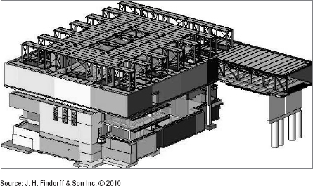
In another example, a Revit model of a project's major building components was linked to the project schedule in Navisworks, creating an animation, as shown here:

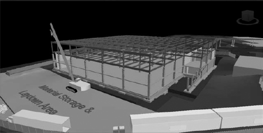
Upon review of the 4D simulation, construction team leaders realized the sequence of the construction would require that structural steel framing from the staging area be hoisted over part of the building that would be occupied. As this was an unacceptable safety condition, the construction sequence was modified, thus avoiding potential delays and unsafe conditions during actual construction.
From the very beginning, the Findorff project management staff realized the power of Revit as a site planning and utilization tool. A site utilization plan can include the basic elements of construction to determine where to place a job trailer or store materials. Families have been developed to represent typical job site elements to expedite modeling of sites, as shown here:

Beyond the placing of basic elements on the site plan, Revit is being utilized to create site models to analyze traffic and circulation patterns and sequencing for delivery of materials. In addition to site utilization, Findorff also uses Revit for schedule coordination, phasing and sequencing studies, detailed staging plans for specific field applications, and clash detection for our MEP trade partners.
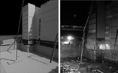
An interesting example of site phasing was a project that required a continuous concrete pour of more than 3,000 cubic yards. To further complicate this process, access to the formwork was more than 30′ (10 m) below grade between and behind four existing buildings. To develop a productive solution to these issues, models of the concrete pump trucks with all of their characteristics for reach, swing, and setup requirements were developed. Then, using the site model and the models of the concrete pump truck, the project managers and site superintendents conducted multiple test layouts in the model, as shown here:

The model was also used to map the site access for all of the concrete trucks, including staging. The pour was completed overnight without moving the concrete pumps or adjusting any of the staging, as shown here. The Revit model is shown on the left. The right image is a photograph from the night of the pour.
USING REVIT DURING CONSTRUCTION
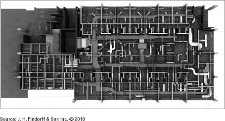
Contractors such as Findorff are finding an increased return on their investment in training and development of BIM resources. During the construction phase, Revit can be one of many valuable tools in a builder's virtual toolbox. An example of this is using Revit models aggregated in Navisworks to allow all MEP trades to merge into the structural and architectural models for spatial coordination (shown here).
CONSTRUCTION SET-OUT DRAWINGS
Concrete and masonry lift drawings are not new to the construction industry. Concrete superintendents and foremen have been doing lift drawings on grid paper by hand for years. Revit simply takes this process to a new level with increased efficiency and information. Findorff creates concrete lift drawings by building their own models of foundations using the architect's and engineer's drawings for reference. This allowed them to create a series of lift drawings based specifically on the exact methods of construction rather than solely on the design intent. One example of such a drawing is shown here:

Such drawings aid in the construction process by clearly identifying the work to be completed. They can contain a variety of intelligent information, including the following:
- Steel embeds
- Concrete openings
- Architectural elements
- Details
- Quantities
- Cost codes
- Labor requirements
Advanced visualization based on accurate modeling techniques can detect potential design conflicts before they can adversely affect the on-site team. Such discrepancies are usually remedied by the modeler and reflected in the lift drawings for little or no cost. If such questions occur in the field during the installation of formwork or during a concrete pour, the cost in lost time would be substantial and probably require expensive change orders.
In addition to detecting and resolving potential conflicts in the execution of the design intent, the construction modeler will engage the project manager and superintendent to determine the optimal sequencing for each concrete pour. All major details associated with each pour are linked to the lift drawings as well as critical information, including volume of concrete, required labor, and productivity measures. These items are all generated from intelligent families of concrete objects that were created within Revit.
The use of modeling for foundations has progressed from simple foundation lift drawings to very sophisticated slab lift drawings, and the level of information and content in the lift drawings has expanded exponentially. Now lift drawings contain openings, sleeve locations, and embed information. In effect, contractors are now producing concrete field shop drawings, even modeling critical rebar areas if a conflict between rebar and formwork is anticipated. Detailed phasing models are also created using view filters to color specific parts of a model based on their construction order, as shown here:
Masonry lift drawings are a natural next step after the development of concrete lift drawings. The productivity savings from completing concrete lift drawings can be equally applied to the development of similar masonry documents. Masonry lift drawings coordinate information relating to masonry work, including but not limited to, openings, elevations, area of insulation, lintels, stone banding, sills, flashing, winter protection, block/brick counts, and manhours, as shown here:
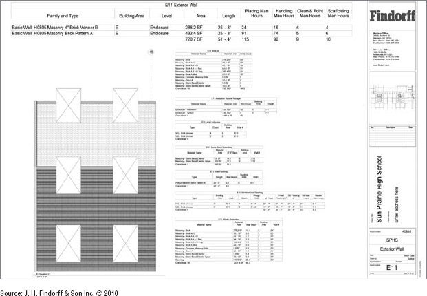
Unlike concrete lift drawings, the breakdown on the pieces became less important and information was given based on individual elevations. The drawings then became planning tools for the field that allowed for more efficient and accurate brick ordering, crew planning, site utilization, staging/delivery management, and constantly updated quantity checks throughout construction. This approach resulted in only a 1 percent variation from what was ordered to what was used.
In the following case study, contributed by Laura Handler of Tocci Building Corporation, you'll find that Tocci uses Revit in a different way from Findorff. While the previous case study focused on an implementation of what you might call lonely BIM, the following illustrates a company dedicated to the notion of social BIM. This case study examines how Tocci applies the principles of integrated design and project delivery in a collaborative environment with a project's design team.
![]() Real World Scenario: CASE STUDY: TOCCI BUILDING CORPORATION
Real World Scenario: CASE STUDY: TOCCI BUILDING CORPORATION
Tocci Building Corporation (www.tocci.com) provides building and construction services throughout the Northeast and Mid-Atlantic, as well as program management and team integration throughout the United States. Through its affiliate company, Q5 LLC (www.q5thecompany.com), Tocci provides virtual design and construction (VDC) and integrated project delivery (IPD) facilitation to projects around the world. Managed by third-generation CEO (Chief Enabling Officer) John Tocci, the company began investigating and testing BIM software tools as early as 1999. By 2006, Tocci had selected the Revit suite of products for model authoring and mandated full use of VDC on all projects. Since then, Tocci has built a robust VDC team and trained all employees to utilize models on a day-to-day basis on projects.
Tocci performs work in the institutional, hospitality, and commercial markets and is nationally known as a leader in VDC and IPD. In 2009, Tocci completed the first pure IPD project on the East Coast, the Autodesk AEC Headquarters, with KlingStubbins and Autodesk, Inc.
CONSTRUCTION VISUALIZATION
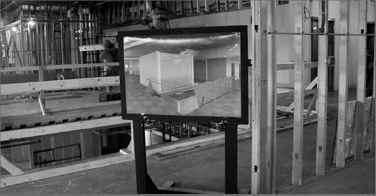
Tocci is nationally known as a leader in virtual design and construction and has been implementing Revit for many years. They have used it in ways similar to those described in the previous case study on Findorff. Simple massing models are used to visualize major project phasing milestones, schedules and color filters facilitate preconstruction planning, and material quantities are extracted from the model to generate accurate bills of materials. One simple and innovative way Tocci utilizes the visualizations of a data-rich building information model is by placing high-resolution renderings throughout the job site. These images are extracted directly from the Revit project using camera views situated according to key work areas requiring clarification, as shown in the following graphic. This enables subcontractors to better understand the overall design intent of a space while they execute their part of the work.
Another specific example of construction visualization is Tocci's use of phasing in Revit and some manual organization of geometry to generate visual construction phase projections—also known as a look-ahead. You can split objects such as walls and floors and then place them in specific phases, one for each week of a construction phase projection. Phase placement will drive both the data in your Revit views as well as quantity information in schedules, so it is critical that it is done carefully.
Using phase filters applied to 3D views shows where the project should be at the end of the week. The phase-filtered schedules communicate the picks of steel and volume of concrete to be poured that week (as shown here). For this project, the three-week projections were used to order materials and to communicate to subcontractors. This process helped keep the project on schedule and reduced material waste.

PLANNING FOR INTEGRATED PROJECT DELIVERY USING BIM
As described in Chapter 7, “Working with Consultants,” collaboratively working in Revit requires advanced planning, often taking shape in the BIM execution plan (BEP). Although the BEP covers all BIM use on a project, Revit standards and protocols will be a large part of the BEP if a team elects to use Revit for model authoring or other BIM uses.
Although there are many BEP templates out there, including the buildingSMART Alliance's BIM Project Execution Planning Guide, Tocci Building Corporation uses an internal template that was originally developed in 2006 and has been continually refined since then. The concept of a BIM execution plan was developed in a digital charrette between Johnson & Johnson, KlingStubbins, Tocci Building Corporation, and EMCOR through the BIMForum (www.bimforum.org) to jointly streamline the BIM-enabled process. The concept was incorporated into ConsensusDOCS 301, BIM Addendum as the documentation that defines the level for which a building information model or models may be legally relied on. It has been incorporated into many other documents since then.
The BEP template and planning process described here was used by Tocci Building Corporation and KlingStubbins on the Autodesk AEC Headquarters, in Waltham, MA, the first pure IPD project on the east coast of the United States. On this project a single building information model, made up of several linked Revit files, was used during design and construction.
Step 1: Picking the People Before any BIM planning can be done, the BIM leads on the project must be determined. A BIM lead represents one of the BIM-enabled major project participants on the project. Start by selecting a BIM lead to represent architecture, construction, and the owner, if each party is BIM-enabled. Select BIM leads to represent other design disciplines or subcontractors as needed. BIM leads should be actual project participants and possess technical BIM experience as well as a disposition toward collaboration.
Step 2: Reviewing the Project Phases The project phases and schedule should be reviewed, so the BIM leads can plan BIM use and standards over the course of the project. Include these in the BEP for reference.
Step 3: Determining BIM Uses Although a BIM can be used in a multitude of ways, each project will use a model in different ways due to the constraints of the project (schedule, complexity, needs, or team members). Determining BIM uses in the planning process will help your team focus on the most appropriate level of detail and model collaboration protocols. A list of potential BIM uses can be found on the Penn State website for BIM Project Execution Planning at www.engr.psu.edu/ae/cic/BIMEx. This list includes information specific to each use, including potential value, resources required, and team competencies required.
Step 4: Selecting Software Given the large number of software programs available, it is often difficult to figure out which ones are necessary. However, once you determine your BIM uses, project software selection will become clearer. The BIM leads may need to engage design consultants or subcontractors to make the final selection.
Step 5: Establishing Standards For each discipline, standards must be set forth for model authoring. Additionally, software-specific standards should be set for each software program needed. Because many participants will already have company-wide standards set up, compromise will be required during this step. Some of the shared standards to consider for Revit include the following:
- File-naming conventions
- Component-naming conventions
- Material-naming conventions
- Workset organization
- Phasing standards
- Shared parameters
- Units and tolerance requirements
Step 6: Determining Model Access With so many entities involved in Revit with an IPD project, access rights will need to be determined. For each model and person, think about the following questions:
- Is live access needed or would a regular update suffice?
- Does the person need to make edits to or extract information from the model?
- Do they require model geometry or just parameters?
- Does the participant just need to view the model?
Answering these questions helps determine if the participant should access the model live via VPN or by co-locating, versus downloading the model regularly via tools such as FTP. It will also help determine what software each person needs and if certain parts of the model should be restricted (if that is technically possible).
Step 7: Defining the Level of Detail One of most time-consuming parts of BIM execution planning is determining the level of detail required at each stage for each component type. This is casually referred to as “who models what, when, and how.” For each object type, detail geometry definitions and parametric information required at each project stage is documented based on the project BIM uses. With walls, for example, this includes making decisions on the following:
- When walls need to change from nominal to actual dimensions
- When layers need to be defined
- When layers need to be broken
- When and how fire-rating data is input
- What parameters wall tags will display
Step 8: Mapping Workflows for Model Uses A workflow needs to be defined and documented for each BIM use, so all parties understand the details of the use and how it fits into the overall project. Workflow is often discussed with level of detail (LOD), but it needs to be focused on and finalized. A simplified example is shown here:

DESIGN TO FABRICATION
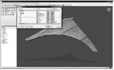
In the IPD project for Autodesk's AEC Headquarters, KlingStubbins and Tocci had utilized, to the greatest extent possible, a process that supported the stewardship of data from the earliest design concepts through fabrication and installation. This process is perhaps best illustrated in the development of custom wood ceiling panels for a special customer area of the project. After a concept was conceived by the architect with input from the builder and fabricator, custom families in Revit were created to optimize the layout of the panels.
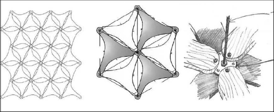

Once the panels were arranged throughout the space in the desired configuration, modelers from KlingStubbins and Tocci were able to collaborate with fabrication modelers at RB Woodcraft in Syracuse, NY, to further refine the design based on optimal constructability. Autodesk Inventor was then used to assimilate the form and generate 2D shop drawings.
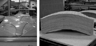
When the custom panels were installed, it completed the vision of both the design and construction team while controlling cost, reducing waste, and keeping the project on schedule.
