
Creating Details
Even when creating details, Revit has a variety of parametric tools to allow you to leverage working in a BIM model. You can use these tools to create strictly 2D geometry or to augment details you are trying to create from 3D plans, sections, or callouts. To become truly efficient at using Revit to create the drawings necessary to both design and document your project, it's important to become acquainted with these tools—you will find yourself using them over and over again throughout your process.
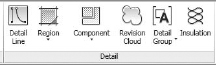
All of these view-based tools are located on the Detail panel of the Annotate tab (Figure 17.1). This small but very potent toolbox is what you will need to familiarize yourself with in order to create a majority of the 2D linework and components that will become the details in your project. To better demonstrate how these tools are used, let's step through each of them.
FIGURE 17.1 The Detail panel of the Annotate tab
Detail Line
The Detail Line tool (Figure 17.2) is the first tool located on the Detail panel of the Annotate tab. This tool is the closest thing you'll find to CAD drafting. It allows you to create view-specific linework using different line weights, tools for drawing different line shapes, and many of the same manipulation commands you would find in a CAD program.
FIGURE 17.2 The Detail Line tool
![]()
Detail lines are view specific—they will only ever appear in the view in which they're drawn. They also have an arrangement to their placement, meaning that you can layer them underneath or on top of other objects. This is especially important when you begin using regions, detail lines, and model content to create your details.
Using the Detail Line tool is fairly easy. Selecting the tool will change your ribbon tab to look like Figure 17.3. This new tab will have several panels that allow you to add and manipulate linework.
FIGURE 17.3 The Detail Line toolset

There are three major panels on this new tab: Modify, Draw, and Line Style. Because of their use sequence (selecting the line type, creating the shape, and modifying the line), we'll talk about them in order from right to left.
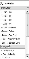
Line Style This panel is a drop-down menu that allows you to choose a line style and line weight in which to produce the linework in this view. This drop-down (Figure 17.4) has all the default Revit line styles as well as any custom ones you might have made for your project or to accommodate office standards. The active line will be the one displayed in the drop-down window before it's expanded.
FIGURE 17.4 The Line Style drop-down menu
New line styles can be added at any time in the project, and many offices find it necessary to add custom line styles beyond the Thin, Medium, and Wide ones available in Revit out of the box. To add more styles or to just see the complete list, choose Additional Settings from the Manage tab and select Line Styles (Figure 17.5).
FIGURE 17.5 Modifying the line styles

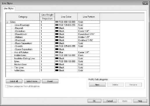
This opens the Line Styles dialog box. When you expand the Lines node at the top, Revit reports a full list of the line styles available in the model (Figure 17.6). Keep in mind that the listed line weight is relative to the scale of the view and scales automatically.
FIGURE 17.6 The Line Styles dialog box
Draw The Draw panel (Figure 17.7) contains a number of shapes that are quickly available to draw within your view. The tools allow you to create lines, boxes, circles, splines, ellipses, and arcs. The last tool in the bottom row is the Pick tool. This tool allows you to select a line or portion of a model element (say an edge) and add a line over the top of it.

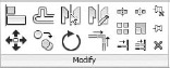
Modify The Modify panel (Figure 17.8) allows you to modify any of the linework already placed within the view. This panel contains several tools you can use to modify lines. Tool icon size is based on frequency of use; the larger icons are the tools you will tend to use most. The larger tools, from left to right, are Align, Offset, Mirror (axis), Mirror (line), Move, Copy, Rotate, and Trim.
Regions
![]() The next tool on the Detail panel of the Annotate tab is the Region tool (Figure 17.9). Regions are areas of any shape or size that you can fill with a pattern. This pattern (much like a hatch in AutoCAD) will dynamically resize with the region boundary. Regions layer just like detail lines do and can be placed on top of or behind linework and model objects. Regions also have an opacity and can be completely opaque (covering what they are placed on) or transparent (letting the elements show through).
The next tool on the Detail panel of the Annotate tab is the Region tool (Figure 17.9). Regions are areas of any shape or size that you can fill with a pattern. This pattern (much like a hatch in AutoCAD) will dynamically resize with the region boundary. Regions layer just like detail lines do and can be placed on top of or behind linework and model objects. Regions also have an opacity and can be completely opaque (covering what they are placed on) or transparent (letting the elements show through).
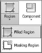
There are two types or regions: filled regions and masking regions. Filled regions allow you to choose from a variety of hatch patterns to fill the region. These are commonly used in details to show things like rigid insulation, concrete, plywood, and other material types. Masking regions, on the other hand, come in only one flavor. They are white boxes that can have (or not have) discernable borders to them. Masking regions are typically used to “hide” or mask certain content from a view that you don't want shown or printed.
When selecting the Region tool, you will be taken directly into Sketch mode, and you'll have a series of tools similar to those for drawing detail lines. The Draw panel allows you to create any number of shapes with all the associated tools to move, copy, or offset the linework.
When creating either kind of region, it's important to note that you cannot complete Sketch mode unless the region is a closed loop. This means that there needs to be a continuous, closed line that creates one single shape. Multiple shapes are not supported when making regions. If you need more than one shape, you'll have to create more than one region.
Another aspect of regions is the linework that borders the region. When beginning the Region tool, you'll be able to choose the line style from the Line Style drop-down (similar to creating detail lines) that you want to use for the border of the region. You can change line styles for any of the segments of the region and even make them all different if needed.
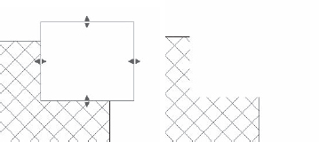
One especially useful segment line style is the <Invisible> line. When drawn in Sketch mode, this appears as a gray line, but once the sketch is completed, it becomes an invisible line, allowing you to create boxes or other region shapes without discernable borders. When used with a masking region, it can create a completely invisible box that allows you to hide elements that are unwanted in a particular view. Figure 17.10 shows the same masking region in two instances, one selected and the other not selected. You can see how the masking region visually disappears, covering the filled region.
FIGURE 17.10 A masking region selected and not selected
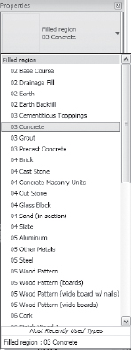
Filled regions have slightly more options since, unlike with a masking region, you can control the region's pattern. When selecting the Filled Region tool, you'll still need to create a boundary for the region to fill. Now, however, you can also select a region type from the Properties palette (Figure 17.11). Region types are another type of Revit family. Creating a region type in one view allows the same region to be used in any other view, and modifying the properties of a region in one view changes it in all the other views.
You'll notice that many of your region names in Figure 17.11 show material types. You'll typically end up using several common material types, so it's a good idea to get these regions into your office template.
FIGURE 17.11 Selecting a filled region type from the Type Selector
STANDARDIZING REGION NAMES
Having some sort of standard applied to your region names can help you organize the Filled Region drop-down in a logical way that is easy for the project team to understand. You'll notice in Figure 17.11 that we've organized the region names around a two-number MasterSpec division prefix. Since MasterSpec is tied to the keynoting system as well, project teams tend to be familiar with the naming convention. This approach also keeps similar material types sorted together rather than sorted alphabetically. Take Concrete and Precast Concrete as an example. You can see in Figure 17.11 that those material types are very close together in the drop-down list based on their prefix.
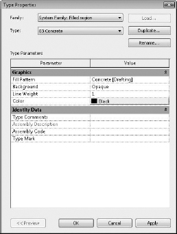
The filled regions also have additional properties. By highlighting any placed region, you can go to its type properties (Figure 17.12). These properties allow you to control the fill type, opacity, line weight, and color of the region.
FIGURE 17.12 Type properties for a filled region
FILLED REGION TYPES
Beyond the ability to control opacity (transparent or opaque), two other filled region types are available. These types, Model and Drafting, create region patterns with different properties and will scale in different ways. You can create both of these regions by opening the Filled Region properties and clicking Duplicate.
Drafting Regions
Drafting regions (Figure 17.13) are a region type typically used for patterns. Some examples of a drafting region hatch might be diagonal lines in an area plan, or crosshatched lines to show the difference between two departments.
FIGURE 17.13 Filled Region drafting patterns
Drafting regions are created by specifying a distance between two or more lines relative to the printed sheet. In the example of diagonal lines, you might adjust the properties so the lines are ¼″ apart. This means that regardless of the view scale, the diagonal lines will always be ¼″ apart on the printed sheet. As you scale the view up or down, the lines will appear closer or farther apart, with the sheet view always remaining consistent.
Model Regions
Model regions (Figure 17.14) are the other type of filled region you can create. Model regions keep a consistent spacing relative to the model, not the view. You might use a model region to show ceiling tiles or brick courses, or to show a 4″ grid in a bathroom tile pattern. Model regions behave as if they've been “applied” to the surface and will rotate and move with the surface. So, in the example of a 4″ bathroom tile, you would create a 4″ perpendicular crosshatch model pattern. As you change the scale of the view this region is inserted into, the lines within the region will always be 4″ apart while they will appear closer together or farther apart on the printed sheet.
FIGURE 17.14 Filled Region model patterns
CREATING A NEW FILLED REGION TYPE
To create a new filled region type, begin by duplicating an existing region and modifying its properties. To create a new type, follow these steps:
- Select the Filled Region tool and click the Edit Type button in the Properties palette.
- Click Duplicate in the Type Properties dialog box.
- Name your new region type and click the button in the Fill Pattern field.
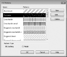
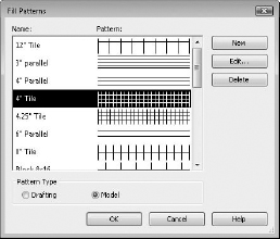
- Make sure you have the proper type of filled region (Model or Drafting) selected at the bottom of the Fill Patterns dialog box; then click the New button.
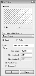
- In the New Pattern dialog box (Figure 17.15), you'll have two additional options for creating a pattern. To create a simple pattern, choose the Simple option. This lets you create a pattern based on a regular line spacing that is parallel or perpendicular to the other lines in the pattern. Selecting Drafting or Model orients the spacing to the sheet view or the model accordingly.
FIGURE 17.15 New Pattern dialog box
For more complex pattern types, you can choose the Custom option (Figure 17.16). Here, you can name the pattern and import one from an external PAT (pattern) file such as an ACAD (AutoCAD database) pattern file. Make sure that when you import the pattern, you scale it exactly how you'd like it to appear. Once it is imported, you cannot rescale the pattern and you will be forced to re-create it.
FIGURE 17.16 Importing custom patterns

- With the pattern type imported or set, click OK. The last variable to set for a pattern type is Orientation In Host Layers (Figure 17.17). This drop-down menu allows you to select from three options for the orientation of the pattern within the region:
FIGURE 17.17 Orientation In Host Layers options

Orient To View This option will keep any directionality associated with the pattern relative to the view. If the view is rotated, the pattern will be rotated, as well. This is also the default selection.
Keep Readable This option will rotate the directionality of the pattern relative to the bottom or right side of the sheet the view is placed on. It will act much like annotation text does and automatically align itself to the nearest readable side.
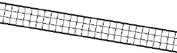
Align With Element This option is specifically useful if you want the orientation of the pattern aligned with the region boundaries. A classic example of this is in rigid insulation. Rigid insulation is typically shown as a perpendicular crosshatched pattern oriented to the slope of the roof. By defining this pattern within the material type for Rigid Insulation, we're able to have the slope of the insulation pattern follow the slope of the roof (Figure 17.18).
FIGURE 17.18 Aligning the pattern with the element
Note that this orientation type doesn't allow you to rotate a filled region—it only associates directionality with model elements.
- When you're finished, click OK until you exit all the dialog boxes. The same region patterns that you've created for a filled region can also be associated with material surfaces or cuts using the Settings
 Materials dialog box.
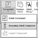
Components
The Component drop-down menu allows you to insert a wide array of component types into your model. These are 2D detail components, or collections of detail components in the case of a repeating detail. Detail components are schedulable, taggable, keynotable 2D families that allow an additional level of standardization within your model. Some examples of 2D detail components are blocking in section, steel shapes, metal studs in plan or section—just about any replicated 2D element that comes in a standardized shape.
DETAIL COMPONENTS
![]() Detail components (Figure 17.19) are 2D families that can be made into parametric content. In other words, a full range of shapes can be available in a single detail component. Because they are families, they can also be stored in your office library and shared easily across projects.
Detail components (Figure 17.19) are 2D families that can be made into parametric content. In other words, a full range of shapes can be available in a single detail component. Because they are families, they can also be stored in your office library and shared easily across projects.
FIGURE 17.19 Detail components

To add a detail component to your drawing, select Detail Component from the Component drop-down list located on the Annotate tab and use the Type Selector to choose from ones that are already inserted into the model. If you don't see a detail component you want to insert in the Type Selector, click the Load Families button on the Modify | Place Detail Component located on the Annotate tab under Detail and insert one from the default library or your office library.
Adding Detail Components and Embellishing the View
Making a detail component is much like creating a 2D family. Let's step through making a simple 2D Detail component.
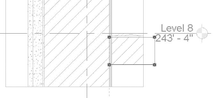
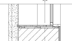
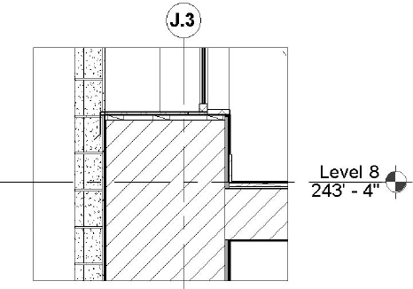
From the book's companion web page (www.sybex.com/go/masteringrevit2012), download the JenkinsMusicBldg.rvt file and open the view Exterior Detl, Typ. You'll create some detail components and regions to get started with a typical window detail. The first thing you'll want to do is use the Callout tool to create a new detail of the window sill. Create a new callout and name it Exterior Window Sill, Typ. The starting view will look like Figure 17.20.
FIGURE 17.20 The window sill detail before embellishment

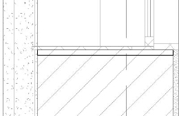
- You'll notice that you have some detail elements that can't exist in real-life construction. For example, you'd never run the sheetrock back behind the floor slab, and there's no room for flashing or blocking below the window. You'll need to modify this view to rectify these conditions. Let's start with the floor slab and fix the sheetrock. To do this, we'll cover a portion of this area with a filled region. Select the Filled Region button from the Annotate tab.
- Set the line style to invisible and create a box bounding the floor slab (Figure 17.21). You'll notice three of the boundary lines are on cut planes: the top and bottom edges of the box. Select these edges and use the Line Style drop-down to change the line weight to Medium.
FIGURE 17.21 Modifying the boundary of the filled region
- Click the Edit Type button in the Properties palette to open the Type Properties dialog box. Since there is no defined region type that is identical to existing materials, you'll need to make one. Click Duplicate, name the new region type 00 Existing, and click OK.
- Now you need to modify the settings:
Fill Pattern: Set this field to Drafting and choose ANSI31.
Background: Opaque
Line Weight: 1
Color: Black
Click OK when you're done.
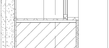
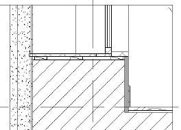
 Now that the region is defined, click the green check mark to complete the sketch. Your finished filled region will look like Figure 17.22.
- Say you know that as part of the window sill condition, you have a 1″ gap between the bottom of the window sill and the existing masonry opening. This isn't reflected in the window detail currently because the window family was created to cut a square opening just big enough for the window. For this detail, you need to create a masking region under the window sill so you can add some other components like blocking. Choose the Masking Region tool from the Region flyout on the Annotate tab.
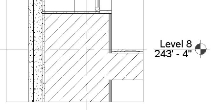
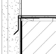
- With Line Style set to Thin Lines, create a box 1″ deep under the window sill (Figure 17.23).
FIGURE 17.23 Adding a masking region
- With the box created, click the green check to complete the sketch. The finished sill will look like Figure 17.24.
FIGURE 17.24 The completed sketch
The next step is to add some detail components for blocking and trim. Click the Application menu, choose New ![]() Family, and choose Detail Component.rft. When creating detail components, as with any other family, you start with two reference planes crossing in the center of the family. This crossing point is the default insertion point of the family. The first family, blocking, is straightforward:
Family, and choose Detail Component.rft. When creating detail components, as with any other family, you start with two reference planes crossing in the center of the family. This crossing point is the default insertion point of the family. The first family, blocking, is straightforward:
- Start by selecting the Masking Region tool on the Home tab and drawing a box with the lower-left corner at the origin. The box should be 1″ high and 3½″ wide. You're using the Masking Region instead of the Lines tool so you can have a clean, white box that you will be able to use to layer over other elements you might not want to see.
- On the Home tab, click the Lines tool and draw a line across the box denoting blocking. The family should look like Figure 17.25.
FIGURE 17.25 Creating a blocking detail component
- With the drawing finished, click the Application menu, select Save As Family, and name the family 06 Blocking. Place it in a folder with the Jenkins model.
- With the family named, click the Load Into Project button to add the family to the Jenkins model.
- On the Annotate tab, click the Detail Component button. The component you inserted will be the one that will become the default component, and you will be able to see the name 06 Blocking in the Type Selector. Insert a piece of blocking at the left, right, and center of the sill (Figure 17.26).
FIGURE 17.26 Inserting and placing the blocking
- With the blocking inserted, you want to make one more detail component for the baseboard. Create a detail component using the same steps as earlier measuring ½″ wide by 6″ high and called 06 Baseboard. The reason you want to create these elements as families and not just as filled regions is so that later in the detailing process you can annotate them using the Revit keynote tool (explained in Chapter 19, “Annotating Your Design”). Families will have a lot more functionality and versatility later down the line for faster documentation. With the baseboard added, the detail looks like Figure 17.27.
FIGURE 17.27 The sill detail with base
- Not all of the detailing will be able to be completed using components. Sometimes, it is easier and more effective to simply use linework to create the necessary features in a detail. For these purposes, you want to create some flashing at the window sill. To do this, we're going to use the Detail Line tool. Choose the tool and choose Medium Lines from the Line Style drop-down menu.
- Using the Detail Line tool, draw in some flashing for the window sill (Figure 17.28).
FIGURE 17.28 Adding flashing using detail lines
Arranging Elements in the View
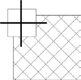
So far you have created all of the content in order and have not had to change the arrangement of any of the elements. However, knowing how to change arrangement is an important part of detailing so you don't have to draw it all in exact sequence. Arrangement allows you to change the position of an element, such as a line or a detail component relative to another element. Much like layers in Photoshop or arrangement in PowerPoint, Revit allows you to place some elements visually in front or behind others. Once an element or group of elements is selected and the Modify menu appears, on the far right you'll see the Arrange panel (Figure 17.29).
FIGURE 17.29 The Arrange panel

From here, you can choose among four options of arrangement:
Bring To Front This brings the selected objects all the way to the front of the stack. In Figure 17.30, you have two detail lines on top of a masking region, which is also on top of a filled region. Select the detail lines and choose Bring To Front, and the lines are now on top of all the other elements.
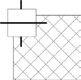
Bring Forward This option brings the selected elements one step closer to the front in a given sequence. In Figure 17.31, we've selected the masking region and chose Bring Forward, and now it appears on top of one of the detail lines. Note that each of the detail lines is its own layer within this stack.
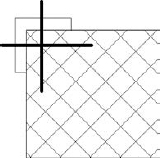
Send To Back This option does the exact opposite of the Bring To Front tool and will send an object all the way to the back of the stack. In Figure 17.32, we've chosen the masking region again and sent it to the back.
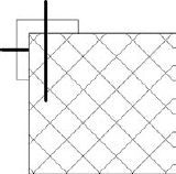
Send Backwards The fourth option, Send Backwards, will step the selected elements one step backward in the stack. In Figure 17.33, we've chosen the horizontal detail line and sent it backward; it now appears behind the filled region.
REPEATING DETAIL COMPONENT
![]() Repeating elements are common in architectural projects. Masonry, metal decking, and wall studs are some common elements that repeat on a regular interval in architectural projects. Revit's tool to help create and manage these types of elements is called the Repeating Detail Component and it's located in the Component flyout on the Annotate tab (Figure 17.34).
Repeating elements are common in architectural projects. Masonry, metal decking, and wall studs are some common elements that repeat on a regular interval in architectural projects. Revit's tool to help create and manage these types of elements is called the Repeating Detail Component and it's located in the Component flyout on the Annotate tab (Figure 17.34).
FIGURE 17.34 Choosing Repeating Detail Component
This tool lets you place a detail component in a linear configuration where the detail component repeats on a set interval. This allows you to draw a “line” that then becomes your repeating component. The default Revit repeating detail is common brick repeating in section (Figure 17.35). Creating elements like this not only lets you later tag and keynote the materials, but also gives you some easy flexibility over arraying these elements manually.
FIGURE 17.35 A brick repeating detail

Before you create a repeating detail component, we'll cover the properties behind one so you can get a better idea of how they work. Selecting the Brick component and choosing Edit Type gives you the Type Properties dialog box shown in Figure 17.36.
FIGURE 17.36 Type Properties dialog box for a repeating detail
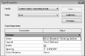
Here's a brief description of what each of these settings does:
Detail This setting allows you to select the detail component to be repeated.
Layout This option offers four different modes:
Inside This option adjusts the start point and end point of the detail components that make up the repeating detail.
Spacing This option is active only when Fixed Distance or Maximum Spacing is selected as the method of repetition. It represents the distance at which you want the repeating detail component to repeat. It doesn't have to be the actual width of the detail component.
USING REVIT TO PERFORM MATH
In the example of the brick, you have a distance of 2 171/256″. Since brick repeats every three bricks in 8″, you don't have to know the exact distance between each brick. Revit is formula driven, so you can enter 8″÷ 3 into this field, and it will calculate the distance for you.
Detail Rotation This option allows you to rotate the detail component in the repeating detail.
With these settings in mind, you need to create a custom repeating detail for the sill detail you've been working on. The exterior of the building is terracotta brick and will have visible joint work every 8″.
- Begin by selecting a new Detail Component family. Click the Application menu, select New Family, and choose Detail Component.rft from the list.
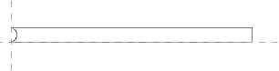
- Create a masonry joint 6″ long and ⅜″ high with a strike on one of the short ends (Figure 17.37) using a filled region. Save the family as 04 Grout and load it into the project.
FIGURE 17.37 The grout detail component
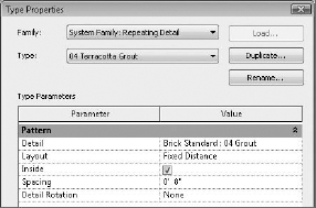
- Now, back in the project, choose the Repeating Detail Component tool. Choose Edit Type from the Properties palette and Duplicate from the Type Properties menu. Name the new type 04 Terracotta Grout and click OK.
- You need to change the properties of this new type to reflect the detail component you just created and its spacing. Change the following fields:
Detail: Set this to 04 Grout, the family you just created.
Spacing: Set this value to 8″.
You can leave the rest of the fields alone. Click OK when you're finished. The type properties will look like Figure 17.38.
FIGURE 17.38 The repeating detail's type properties
- Since you're still in the Repeating Detail command, you can simply begin drawing a “line” with the repeating detail. Starting at the base of the view, draw a line all the way up the left edge, placing the new joint over the terracotta exterior.
- You can further finesse the appearance by placing one of the joints directly below the window sill. This will appear placed on top of the flashing you drew earlier, so select the flashing detail line and choose Bring To Front. The completed detail will look like Figure 17.39.
FIGURE 17.39 The finished window sill detail
Although this detail still needs annotations before you could think about placing it onto a sheet, you can begin to see how you have used the 3D geometry of the model and were able to quickly add some embellishment to it in order to create a working project detail. For now, save this detail. You'll return to it later in the chapter.
Insulation
The best way to think of the Insulation tool is like a premade repeating detail. You'll find this tool on the Detail panel of the Annotate tab (Figure 17.40).
FIGURE 17.40 The Insulation tool
![]()
Selecting this tool allows you to draw a line of batt insulation, much like a repeating detail. Figure 17.41 shows a typical line of insulation.
FIGURE 17.41 The insulation in the model
![]()
When selecting the insulation tool, you can modify the width of the inserted insulation from the Options Bar (Figure 17.42). The insulation is inserted using the centerline of the line of batt, and you can shorten, lengthen, or modify the width either before or after inserting it into your view.
FIGURE 17.42 Modifying the Insulation width in the Options Bar
![]()
Detail Groups
Detail groups are similar to blocks in AutoCAD and are a quick alternative to creating detail component families. They are collections of 2D graphics and can contain detail lines, detail components, or any collection of 2D elements. While you will probably want to use a detail component to create something like blocking, if you plan to have the same blocking and flashing conditions in multiple locations, you can then group those conditions and be able to quickly replicate them in other details. As with blocks in AutoCAD, manipulating one of the detail groups will change all of them consistently.
There are two ways to make a detail group. Probably the more common is to create the detail elements you'd like to group and then select all of them. In the contextual Modify tab that shows up, click the Create button (Figure 17.43). When you're prompted for a group name, name the group something clear rather than accepting the default name Revit wants to give it (Group 1, Group 2, and so on).
FIGURE 17.43 Selecting elements and then creating a group using the Modify menu
![]()
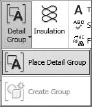
The other way to create a detail group is by clicking the Create Group button in the Detail Group flyout on the Annotate tab (Figure 17.44). You will then be prompted for the type of group (Model or Detail) and a group name before you can select any elements for the group.
FIGURE 17.44 Click the Create Group button on the Annotate tab, and then select the elements.

When selecting the elements, you'll be taken into Edit Group mode. Your view will have a yellow transparency overlaid on top of it, and elements within the view will appear gray. To add elements to the group, click Edit Group ![]() Add (Figure 17.45). Here you can also remove unwanted elements from your group. When you're finished, simply click the Finish green check mark.
Add (Figure 17.45). Here you can also remove unwanted elements from your group. When you're finished, simply click the Finish green check mark.
FIGURE 17.45 The Edit Group panel

You can place any group you've already made using the Place Detail Group button from the Detail panel of the Annotate tab (Figure 17.46). Groups insert like families, and you can choose the group you'd like to insert from the Type Selector on the Properties palette.
FIGURE 17.46 Inserting a detail group
Linework
![]() Although not part of the Annotate tab, the Linework tool is an important feature in creating good line weights for your details. Revit does a lot to help manage your views and line weights automatically, but it doesn't cover all the requirements all the time. Sometimes the default Revit lines are heavier or thinner than you'd desire for your details. This is where the Linework tool comes in handy; it allows you to modify existing lines in a view-specific context.
Although not part of the Annotate tab, the Linework tool is an important feature in creating good line weights for your details. Revit does a lot to help manage your views and line weights automatically, but it doesn't cover all the requirements all the time. Sometimes the default Revit lines are heavier or thinner than you'd desire for your details. This is where the Linework tool comes in handy; it allows you to modify existing lines in a view-specific context.
To use the Linework tool, choose the Linework button from the View panel on the Modify tab. This will add the familiar Line Styles Type Selector panel on the right of the tab and allow you to select a line style from the list. Simply choose the style you want a particular line to look like and select that line in the view. The lines you pick can be almost anything; cut lines of model elements, families, components, whatever. Selecting the line or boundary of an element will change the line style from whatever it was to whatever you have chosen from the Type Selector. Figure 17.47 shows a before and after of your sill detail with the linework touched up.
FIGURE 17.47 Before and after the Linework tool

You can also choose to remove lines using this tool. By selecting the <Invisible> line type, you can make some linework disappear. This is a good alternative to having to cover unwanted linework with a masking region. If you press and release the Tab key as you hover over one line, it highlights the entire chain of lines for selection!
DETAIL COMPONENTS AND PROJECT TEMPLATES
If you find you are inserting the same detail components over and over again, load them into your project templates and make them readily available when you begin any new project.