
Adding Detail Components to Families
Earlier in this chapter, you investigated how to embellish a view by adding detail components, detail lines, and other elements. By doing so, you not only made the detail you were working with more complete, but you also added content to the model that could be reused in other details. Combining these principles, you can extend this theory to family creation where you can modify 3D families to include elements from 2D details.
Since you have the ability to change the level of view detail from Coarse to Medium to Fine within your project, you can use these settings in connection with detail components to modify families and add even more versatility to them. You can begin embedding detail components into the families for typical conditions and eliminate even more repetition when adding components to typical conditions.
Building these types of families is not complicated, but it does require a bit of knowledge about how a family is created and assembled and a bit of planning around the building design and detailing. In the chapter's example, you have found that the window you detailed earlier in this chapter is a typical window and a typical condition in many other parts of the building. Since this window type will show up in all the sections throughout the project, you'll now add some of the common features from the detail components directly to the family so you don't have to draw and redraw them every time this window appears.
Adding Details to a Window Family
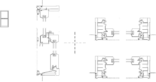
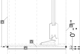
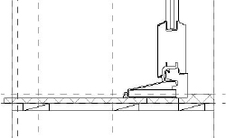
Because you already created the sill condition in the window detail, it will be an easy reference when working on the family. Start by opening the Jenkins model you downloaded earlier in this chapter and locating the Callout Of Exterior Detl, Typ view you have been working on. This view (Figure 17.48) shows a window sill condition with some flashing and blocking.
FIGURE 17.48 The window sill detail

- Begin by selecting a window. Then right click to and select Edit Family from the context menu. The detail you are working from is a section condition and there's no section described in this family. To add one, from the View tab choose the Section tool and cut a section through the plan of the window looking the same direction as your project detail.
- Since you are adding elements to this section, assume you've decided to add some additional information about the window itself. During the course of the design, you've chosen a window manufacturer and gone to their website to download sill, head, and jamb conditions, and you want to create another detail component from this file. Click the Application menu and select New
 Family Detail Component.rft.
 - From the Insert tab, choose Import CAD and navigate to the ASCMDDH3a.dwg file you downloaded from the manufacturer's website (or in this case, from the book's companion web page). Before you import the file, you need to make some adjustments to this dialog box. Change the following fields:
Colors: Black and White
Layers: Specify
Import Units: Inches
This will import the CAD file at the right scale and allow you to choose the layers you want to import. When your dialog box matches Figure 17.49, click Open.
FIGURE 17.49 Importing a CAD detail

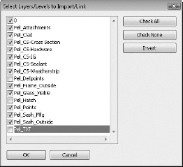
- Before the CAD detail completes its import, you get to choose which layers you'd like to import. When the Select Layers/Levels To Import/Link dialog box appears, uncheck the following layers (Figure 17.50):
Pel_Defpoints
Pel_Hatch
Pel_TXT
Then click OK.
FIGURE 17.50 Selecting layers to import
The imported CAD file will look like Figure 17.51. You'll need to perform a bit of cleanup before you can make this into a usable detail component.
FIGURE 17.51 The imported CAD file
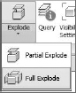
- Highlight the imported CAD file and from the Modify tab choose Full Explode (Figure 17.52). This will break the CAD file down into individual components and allow you to not only edit some of the level of detail but also remove elements you don't need.
FIGURE 17.52 Exploding the CAD file
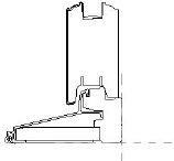
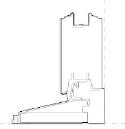
- From this point, you can delete all of the other CAD information except for the sill condition. That bit can also be cleaned up and much of the detail removed. Many times downloaded CAD files have more detail in them than will show well graphically in detail drawings, so cleaning out some of the extra linework will benefit visibility later when you print. The cleaned detail should look like Figure 17.53.
FIGURE 17.53 The final sill detail
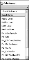
- While the remaining linework is what you want to use in your detail component, you don't want to use the CAD lines that you've imported. You need to convert those line styles to Revit line styles so you don't clutter the project file with extraneous line types. In your window sill detail, select all the linework. Once the lines are selected, choose the Line Styles drop-down menu from the Modify tab. For this detail, you want to change all the line styles to Detail Items, so select that from the drop-down list (Figure 17.54).
FIGURE 17.54 Changing the line styles
- Before you can finish this detail, there is one more element that needs to be added. If the detail was inserted as it is right now, any model elements would appear through the linework, and you want this detail to layer over the top of any other information. To do this, you need to add a masking region around the detail. Choose the Masking Region tool from the Annotate tab and, using the Pick tool, pick the border of the sill detail to form a closed loop and create the masking region shown in Figure 17.55. And as mentioned previously, pressing and releasing the Tab key as you hover over one line highlights the entire chain of lines for selection.
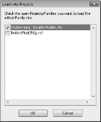
- With the addition of the masking region, you're ready to save the detail and load it into the project. Save the detail to the project's family location and name it 08 Window Sill. When this is done, click the Load Into Project button and load the detail into the Double Hung window family (Figure 17.56).
FIGURE 17.56 Loading the detail into the window family
With the final missing detail component created, you can begin adding the other elements to this detail. You want to create some of the common conditions that appeared in the earlier detail: the blocking, flashing, and masking region.
- In the Section 1 view of the window detail, click the Component button. Start by placing the window sill you just created. Place it over the modeled window so it creates an extension of the existing condition (Figure 17.57).
FIGURE 17.57 Adding the window sill detail to the window family
- Next, similar to how you added additional detail earlier in the project, you will want to embellish this new addition to the detail. Start with the masking region. Select the Masking Region tool from the Annotate tab. Revit will ask you to select a work plane on which to draw your masking region. From the Name list, choose Center, which is the reference plane that cuts the window in half in plan (Figure 17.58).
FIGURE 17.58 Select a reference plane for the masking region.

- Create the masking region the same as before: 1″ tall and the width of the wall (Figure 17.59). Be sure to constrain the vertical dimension to 1″ and lock the other edges to the reference plane (top) and wall edges (left and right). This will allow the masking region to resize with the wall should they be different sizes when the window family is imported into the model.
FIGURE 17.59 Drawing the masking region
- On top of the masking region, you will want to add the blocking. Choose the Detail Component button from the Annotate tab and then choose Load Family from the Modify context menu. Browse to the 06 Blocking family you created earlier and load it into the project. Place the blocking in the same locations you placed it earlier. It should look like Figure 17.60 when finished.
FIGURE 17.60 Placing the 06 Blocking detail component
- As a last item to create, you will need to add the flashing to the detail. In a family, there are no detail lines but instead symbolic lines.
 Symbolic lines are used to show 2D projections or cuts for 3D families. They are commonly used to create any of the 2D linework in a family you will need since not everything in the families are modeled. One of the most familiar uses of symbolic lines is the plan projection of the door swing. In this detail, use the symbolic line Frame/Mullion [Cut] (Figure 17.61) to create the necessary flashing.
FIGURE 17.61 Adding symbolic lines

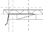
- The finished flashing will look like Figure 17.62. At this point, we're done adding information to the detail, and you can move on to modifying some of the elements we've inserted to add some additional flexibility to the family.
FIGURE 17.62 Finishing the flashing

![]() Real World Scenario: DOORS AND SYMBOLIC LINES
Real World Scenario: DOORS AND SYMBOLIC LINES
In the architecture industry, doors are typically modeled in a closed position but shown as open and with a door swing direction in plan view. To get this dual representation, in the Family Editor turn off the visibility of the door panel (extruded solid form) in the plan view and draw the 90-degree open door panel and its swing using symbolic lines.
Symbolic lines can be controlled using the same visibility settings available for detail components and the solid model elements in the family. You can use the same logic and draw the dashed lines that represent the door opening direction in elevations.
At this point, you could insert the window family back into the project and have it look identical to the detail you created earlier. While it will have the desired look you want, when the detail is drawn at ½″ = 1′-0″ scale (as it is in the project) these additional elements will make the detail look muddled when you show this window at larger scales. So that you can use this same family regardless of scale, you want to modify the Visibility settings.
Visibility Settings
![]() The Visibility Settings tool, found on the Modify tab, allows you to control when elements appear in families based on several variables. Visibility settings are controlled by the Coarse, Medium, and Fine settings for the detail level within a view. These settings are completely independent of any of the family type parameters.
The Visibility Settings tool, found on the Modify tab, allows you to control when elements appear in families based on several variables. Visibility settings are controlled by the Coarse, Medium, and Fine settings for the detail level within a view. These settings are completely independent of any of the family type parameters.
Depending on whether the element you want to control the Visibility settings for is a drafting or model element, you'll have different options to control the visibility. For a model element, you can see from the Family Element Visibility Settings dialog box (Figure 17.63) that you can set if the element is visible in:
Plan/RCP
Front/Back
Left/Right
When cut in section
All of the detail levels (Coarse, Medium, Fine)
FIGURE 17.63 The Family Element Visibility Settings dialog box for model elements

For drafting elements, the number of options is more limited. Since these elements only appear in one view, you have the choice to control the detail level and whether the elements selected are visible when the family is cut in section (Figure 17.64).
FIGURE 17.64 The Family Element Visibility Settings dialog box for drafting elements
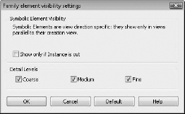
For the detail you have been working on, all of the elements you will want to manipulate are 2D. Select the inserted blocking, sill detail, and masking region and click the Visibility Settings button. Uncheck the boxes for Coarse and Medium detail level. You also want to select Show Only If Instance Is Cut. The Family Element Visibility Settings dialog box should look like Figure 17.65.
FIGURE 17.65 Selecting “Show only if Instance is Cut” from the Family Element Visibility Settings

With this complete, click OK. The modifications to this family are now finished, and you can load it back into the model and test the changes you've made. Click the Load Into Project button.
First, delete the blocking, masking region, and flashing you added earlier in the chapter. Now, you can quickly cycle through the levels of detail to see how the new family's visibility changes with the detail level. Figure 17.66 shows the window sill in Coarse detail. Note that part of your existing conditions for the building show the existing walls in a gray fill. Figure 17.67 shows the wall condition in a Medium detail level. Here you do not yet see the details we've added, but the gray fill is replaced by the masonry hatch. Finally, in Figure 17.68, at a Fine level of detail, you can see the elements you added to the family appear in the view. Since you have this window installed in multiple locations within the model, the same views will be present any time you cut the model in section.
FIGURE 17.66 The Window detail at Coarse

FIGURE 17.67 The Window detail at Medium

FIGURE 17.68 The Window detail at Fine
