
Using Advanced Modeling Techniques
Creating complex geometry isn't always as easy as opening the Family Editor and starting to model the shape that you think you're trying to create. Sometimes you need to model one form in order to create another form. And sometimes you need to model a complex, parameterized form in order to parameterize the actual shape that you're trying to create. So that you understand these advanced techniques, we'll first cover the available geometry types that can be created in Revit.
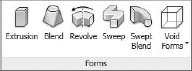
There are five discrete geometry types in the Family Editor: extrusions, blends, revolves, sweeps, and swept blends. Both solid and void forms can be modeled from these shapes.
Which one you select is important, but our advice is to use the simplest form that will express what you're trying to model, keeping in mind how the geometry is likely to change.
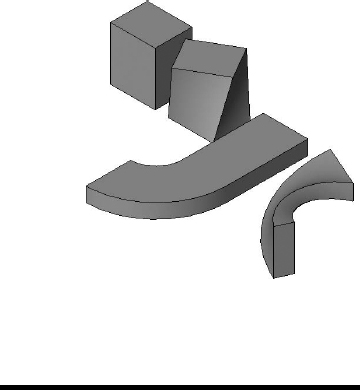
In other words, an extrusion, blend, sweep, and swept blend can be used to create initially similar forms. It's impossible to tell them apart (Figure 15.25). But once these forms change, you'll understand that they can iterate into very different shapes (Figure 15.26).
FIGURE 15.25 Initially similar forms
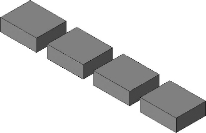
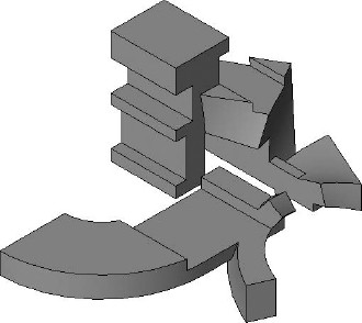
FIGURE 15.26 Left to right: extrusion, blend, sweep, and swept blend
Creating Solid and Void Relationships
One of the great things in Revit is that the relationship between solid geometry and cutting void is nonlinear. Solids that are joined together may still maintain independent relationships. They're not locked together after they're joined.
Additionally, not all voids must cut all solids. The void may selectively cut one solid but not another solid, even though the two solids are joined together. For example, in Figure 15.27 we've joined the solids from the previous image and overlapped them with a single void. Notice how the void is cutting all of the joined solids. Figure 15.28 shows the results of finishing the sketch.
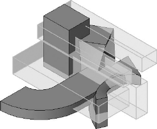
FIGURE 15.27 Single extruded void overlapping all joined solids
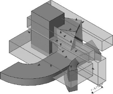
FIGURE 15.28 All joined solids cut
This is often not desirable because now you'll have to go back and “uncut” three of the four joined solids. So in many cases you'd rather model a void that only selectively cuts. The trick here is not to model the void as a void. If you do, then by default it will cut all the solids that came before it. Rather, model the geometry as a solid (Figure 15.29).
FIGURE 15.29 Initially modeling the desired void as a solid

Now you can convert the solid to a void from the Properties dialog box, as shown in Figure 15.30.
FIGURE 15.30 Converting a solid to a void

Figure 15.31 shows the result. The void doesn't cut any of the solids. This result is desirable when you want to complete the void and still see it, because by default, once a void cuts a solid it becomes invisible, which makes it rather hard to find. This technique still shows the void for editing.
FIGURE 15.31 Noncutting voids remain visible.
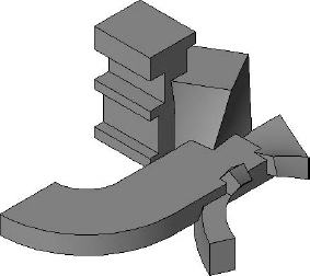
Now you can selectively cut only what you want to cut (Figure 15.32).
FIGURE 15.32 Selectively cutting forms
To review this file, you can download it from the Chapter 15 folder at the book's web page (www.sybex.com/go/masteringrevit2012); it's called Solid Void.rfa.
Carving Geometry
If you're really 3D savvy, creating complex geometry often involves creating what you need with complex modeling tools in order to reach some final result. The process in Revit is often different and has some wonderful benefits as well.
Think of a sculptural process as being additive or subtractive. Creating sculpture as an additive process means that you're casting the desired shape. Creating sculpture as a subtractive process means starting with more stuff than you need and then carving away until you have the final result.
Many complex geometry applications create complex forms as an additive process. In other words, you create a form and then manipulate that result with other tools—pushing, pulling, and twisting until you've morphed the final shape.
Think of Revit as more of a hybrid process that relies heavily on a subtractive approach that carves away what you don't need. Although this may seem a bit counterintuitive at first (because in many 3D modeling tools, cutting geometry is a linear process that doesn't lend itself well to parametric editing), in Revit the void is a live thing that can be quickly and easily modified.
For example, you may not believe that the form shown in Figure 15.33 has been created in Revit. If you're trying to create this form using an additive process, it's quite complicated. But if you create it using a subtractive approach, then it's quite easy, and the results can be surprisingly elegant.
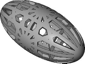
Furthermore, the form consists of only three (copied) extrusions and a single void. But it's easily done and with just a few steps.
![]() Real World Scenario: COMPLEX FORMS MADE SIMPLE
Real World Scenario: COMPLEX FORMS MADE SIMPLE
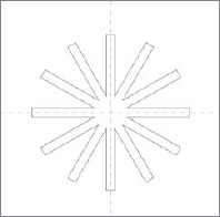
Creating that sculptural form is not hard. Don't believe us? Follow these steps:
- Create the extrusion sketch shown here in a Front/Back elevation. In this case, the overall height is 6′ [2m]. The width is 0′-4″ [10cm].
- When you finish the sketch, set the overall length to 9′-0″ [3m]. This is the resulting shape:

- Go to your Left/Right elevation and use Copy/Rotate to move the form 90 degrees so that the copy is vertical. You'll also have to select the Disjoin option.
- Go to the Top/Bottom view and use Copy/Rotate to move the original form 90 degrees so that the copy is facing left/right.
- Use the Join Geometry tool and join all three forms together. When you're done, the form should look like this:

Now it gets really interesting! We'll show you how to cut multiple solids from a single void after you initially modeled the void as a solid. Here's the sketch of the solid revolve in the Front elevation:

- When you finish the form, you want to make certain that none of the geometry from the star form is showing outside the revolve that you've created, as shown here:
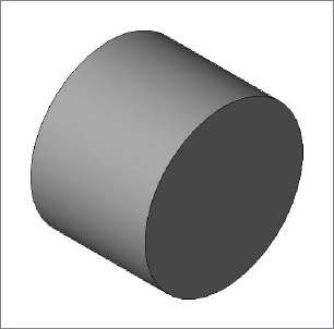
- Change the solid revolve into a void. The void won't cut! This is what you want: the ability to model solids and voids with the flexibility to cut the void when you're ready, not before.

Here's a tip for cutting a lot of geometry with a void without having to select elements one by one. First, select the void and select Cut To Clipboard (or press Ctrl+X). This will remove the void! Don't worry.
- Select Paste
 Aligned To Same Place. Another much less known option is to press Ctrl+V for paste. But when the form starts to hover, select 0, and then press Enter. This will paste the element at 0,0,0, the origin of the original element.
As a result, you should begin to understand that complex form making in Revit is quite often a subtractive process—you create more geometry than necessary and then use a void to carve away what you don't need.

There are some great examples of creating sculptural forms in Chapter 26, “Outside the Box: Film and Stage.” Carving geometry is a technique that set designer Bryan Sutton (profiled in that chapter) uses extensively. If you want to explore this file further, just look in the Chapter 15 folder on the book's web page for the file c15 Egg Sculpture.rvt.
Using Geometry to Drive Geometry
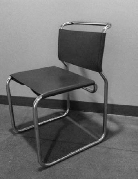
As discussed previously, reference planes, points, and lines are most often used to drive geometric form. If you've been using Revit for any length of time, you've been creating parametric content. But there will be some cases where these three options alone are just not enough. This is particularly difficult with linear or tubular forms, as shown in Figure 15.34.
FIGURE 15.34 Chair with tubular structure
To learn how to drive geometry with geometry, follow these steps:
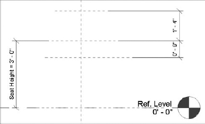
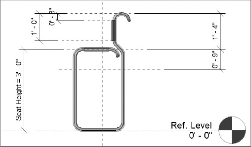
- Open a Furniture template, and add reference planes to control the height of the seatback and the seat. Figure 15.35 shows the reference planes and other locked dimensions.
FIGURE 15.35 Parameterized reference plane
- Now you'll model the “negative space” that would define the centerlines of the tubular structure with a solid extrusion. Make the overall form 20. [6m]wide. Once you finish the line of the inner sketch, simply offset about 1″[3cm] or so (Figure 15.36).
FIGURE 15.36 Extrusion sketch in elevation

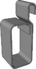
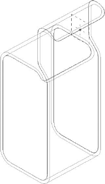
Figure 15.37 shows the finished form. Now you have to start adding the voids that will shape the back of the seat and backrest.
FIGURE 15.37 Finished extrusion
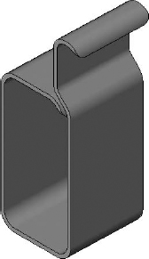
- Create the two individual voids in the Front/Back elevation orientation (Figure 15.38).
When you're done, you've completed a path that represents the path of the structural tubing (Figure 15.39).
FIGURE 15.38 Voids that cut the seat back and seat rest
- Select the Solid Sweep tool and pick the edges that make up the centerline of the structural tubing. Then sketch the profile that you want to follow along this path (Figure 15.40).
FIGURE 15.40 Picking edge-based sweeps
CREATING SEPARATE PATHS FOR COMPLEX SWEEPS
You may find that you're unable to create the edge-based sweep with one continuous path because of the complex curves that happen at the back of the seat and seat rest. Simply create multiple paths where a singular path would break the sketch.
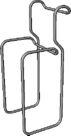
When you finish the path-based sweeps, you'll have the result shown in Figure 15.41.
FIGURE 15.41 Edge-based sweeps with extrusion hidden
- Model the extrusions for the leather seat and seat back. We've also added some additional reference lines to control the vertical location of the leather seat rest (Figure 15.42).
FIGURE 15.42 Additional reference planes
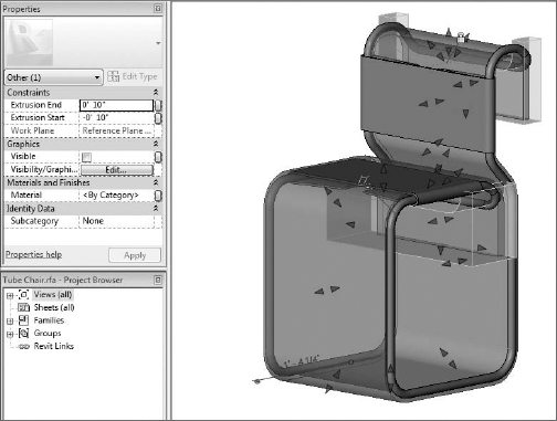
- Now the tubular geometry is being controlled by the extrusion. But of course you don't want to see the extrusion in the project environment. This is easily fixed. Just select the extrusion, and in the Properties dialog box, deselect the Visible option under Graphics (Figure 15.43).
FIGURE 15.43 Deselect the Visible option to hide the extrusion in the project environment.

Once loaded into the project, the extrusion will be hidden, and because of the parameters that drive the extrusion, you can create new types (Figure 15.44).
If you want to explore this file further, just look in the Chapter 15 folder on the book's web page for the file c15 Tube Chairs.rvt.
FIGURE 15.44 Final form in the project environment
