Previsualization in Revit
Remember that when you're designing scenically, you're going to be focusing on maintaining the emotive quality of the design without getting into too much detail. As the design progresses, geometric intent will give way to specific content. But even then, someone will take over what you've started and give the final look and feel to your work. You're not just trying to show the literal geometry of what needs to be constructed—you're also trying to maintain the emotive quality and connection to the earliest production sketches.
Form/Transparency
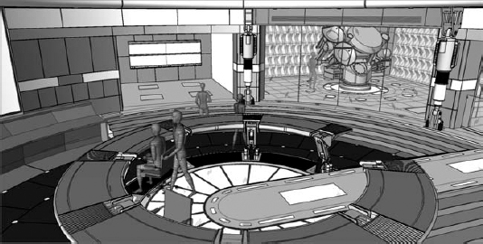
Concentrate on illustrating differences between what is solid and what isn't. The context of what is beyond the immediate space is important. Note the equipment in the room beyond the center space. For example, in Figure 26.12 the materials in Reed's science lab are muted and suggestive—but not too literal. Color is used to distinguish between different materials rather than to express specific materiality.
FIGURE 26.12 View through Reed's lab from Fantastic Four: Rise of the Silver Surfer
TEMPLATE OR NO TEMPLATE?
Surprisingly, Bryan doesn't keep a project template. He says not starting from a template keeps it simple. However, details are often reused, and Bryan has created a set of custom line styles to indicate wild walls (where the walls have deliberately designed breaks so they can be opened for camera access).
Components and system families are not typically reused from project to project in the film industry—everything is highly customized from project to project (unless a sequel is being considered). Rather, Bryan uses a more elegant process of employing generic elements as placeholders during the early design stages. These component and system families are sufficient to indicate the design intent of placement, spacing, and locations—the big ideas of the design. As the design is refined, he'll swap out the placeholders with more specific elements that share the same category and insertion point. Being able to swap out one idea for another quickly and easily is something that Bryan remarks “is what's really nice about Revit.”
Lighting/Shadows
Even before materials are assigned, lighting plays an important role in adding emotive, dramatic context to the design. You have a couple of options since Revit allows shadows in real time but only a single light source, as illustrated in Figure 26.13. Beyond this you're going to need to render.
FIGURE 26.13 Real-time shaded view

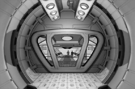
While the objects in Revit can contain the actual lights that can be controlled at time of rendering, this may not be enough. So keep in mind that studio lights (lights without lighting fixtures—just the light source) can be added to the project as well, a technique that was used to visualize Figure 26.14. These kinds of lights are useful for overdramatizing lighting effects and overcoming otherwise hard edges of shadows at the time of rendering.
FIGURE 26.14 Rendered view through the airlock, Fantastic Four
Materials
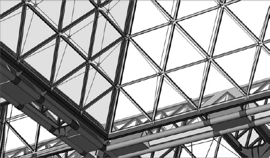
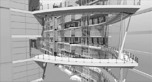
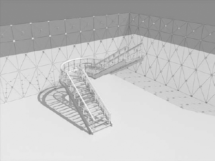
When materials are added, they're probably going to be understated during the design process. More detailed and specific materials assignments will be assigned by CGI artists (who will probably benefit from using your files as a starting point). In Figure 26.15, the horizon is being subtly suggested—but not as a hard, horizontal line in the distance that separates earth from sky. Any more detail would be a distraction!
FIGURE 26.15 Rendering of walkway structure, I, Robot
Rendering and Visualization
Renderings are critically important to the design process in the film industry, and you'll have to communicate simultaneously with regard to form, space, lighting, material, opacity, transparency, and so on, as shown in Figure 26.16. But in some cases, you'll want to be able to render one theme at the exclusion of others.
FIGURE 26.16 Creating a matte-rendering filter

Rendering conceptually as any solid color is a quick way to rationalize and objectify the design. This can be quickly and easily done in Revit using phasing. All you need to do is create a new phase filter called Matte Rendering. Be sure all the phase filter assignments are set to Overridden. (To learn more about phasing, see Chapter 11, “Phases, Groups, and Design Options.”) This is shown in Figure 26.17, as phase filters are being overridden; Figure 26.18 illustrates material assignments associated with a particular phase.
FIGURE 26.17 Overriding phase filters

FIGURE 26.18 Applying material assignments via phasing

Using the Phasing dialog box, set the Graphic Overrides values of both shaded and rendered material assignments of the Complete phase to a solid, white (or off-white) matte material, as shown in Figure 26.19.
Create a 3D view, then open the View Properties dialog box and set Phase Filter to Matte Rendering. Figure 26.20 and Figure 26.21 show the results (before and after).
FIGURE 26.19 Overriding the surface and materials

FIGURE 26.20 Rendered without glass

FIGURE 26.21 Rendered with glass

When you render with these settings, the result will be a monolithic scene that doesn't require you to manually manipulate the materials one by one for shaded views or renderings.
Keep in mind when using this technique that glass will render as opaque. If you want to render with glass as translucent, you'll want to render twice and create a composite view. First, turn off any glass via Visibility Graphics (Categories or Subcategories), and then render the view. Now create a composite view with the glass turned both on and off, and then set the transparency of the view with the glass turned on to around 20 percent. Figure 26.22 shows the final result.
FIGURE 26.22 Final composite view

Creating a hidden line composite view is just one more step beyond creating a composite rendered view (Figure 26.23). Hidden lines are helpful for distinguishing objects that are small, translucent/transparent, or at some distance from the viewer because they accentuate the edges of objects. In these cases you can export a hidden line view and then overlay with a rendered view in order to accentuate edges (Figure 26.24).
FIGURE 26.23 Hidden line export

FIGURE 26.24 New composite view
With this kind of composite view, it's easy to see why they're so effective and desirable. In Figure 26.25, it's apparent that important details are missing! But in the next image, the details are clearly visible through highlighting the edges of those objects from an exported hidden line view (Figure 26.26).
FIGURE 26.25 Detail before hidden line composite
FIGURE 26.26 Detail after hidden line composite

Photorealistic Renderings
Photorealistic renderings are certainly important to the design process as a set designer, but if your work is meant to resolve constructability, it may turn out that you're not responsible for creating highly emotive, finished views. Be aware that from within Revit, you are limited to the geometry that is in the Revit file.
But even if Revit were capable of creating any form imaginable, keep in mind that another person needs to render in their language of choice. And after years of fluency in one language, it's not likely that they're going to change languages to render in Revit. Additionally, they'll subject their renderings to significant postproduction in an image editor. So, be prepared to work with the visualization specialist by exporting Revit to another format (DWG, 3DS, FBX, and so on).
Exploded Views
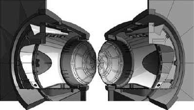
Live exploded 3D views can be quickly and easily assembled in a couple of ways. The first technique involves creating a section box around part of your project and then selecting and copying this section box (Figure 26.27). Copying a section box automatically creates another section box with the same view.
FIGURE 26.27 Real-time section views through airlock, Fantastic Four
Another option is to isolate elements in duplicated views (with or without a section box). When you assemble the views together (on a sheet), you'll be able to pull them apart, creating the effect that the object is being pulled apart. This will help illustrate individual elements that will be prefabricated for assemblage.
Revit to CGI Workflow
According to Bryan, the film and stage industries in Vancouver overwhelmingly use Maya. And before FBX exporting, getting your file to a usable format wasn't always too successful. Fortunately, FBX has really helped. But in some cases you'll export to 3DDWG (and usually as ACIS solids). Autodesk Mudbox is frequently used for high-resolution close-ups (ZBrush).
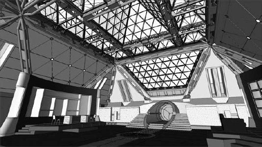
Your Revit file is often a useful starting point for the CGI work that complements the physical sets, which can be exquisitely detailed, as in the Karnak main hall in Watchmen (Figure 26.28). What's nice is that everything should line up between the physical and digital designs. But don't be alarmed if much of your work needs to be rebuilt in Maya.
FIGURE 26.28 Karnak main hall, Watchmen
First, people like to have full control in a familiar language (application) that they have used for years. The deadlines are demanding and there's no room for unpredictable outcomes. Since Maya is being used extensively in the industry, it's likely that Revit files will get leveraged in Maya.
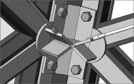
Second, the level of detail that you've produced in your Revit file (you know—the level of detail that is way beyond standard architectural practice) will likely be unnecessarily high for the CGI artist, as illustrated in Figure 26.29. Rendering is still incredibly expensive and time consuming. So any shortcuts to shorten rendering times (without sacrificing quality) are welcome. As a result, the CGI artists often use materials to represent granular geometric details—the kind of details that you've just modeled with geometry in Revit to resolve construction (Figure 26.30)!
STACKING VIEWS
You should anticipate how the views should stack. It's not yet possible to reorder the front/back relationships of views after the views have been placed on sheets. So the views in the background need to be placed on the sheet first and the views that need to be in the foreground should be placed last. The image shown here displays the real-time exploded views through the airlock on Fantastic Four:

FIGURE 26.29 Karnak glazing detail