Using Revit in the Design-to-Production Process
Using Revit in the architectural profession has unique processes and characteristics. The same is true in the production process of film and stage set design. Of course, there's going to be some overlap considering that both spaces need to be occupied by people. But you'd be surprised how little real architecture exists in the set design industry.
In this section, we'll walk you through the process of using Revit in the film and stage industries. And since you're familiar with the industry, only Revit might be unfamiliar. But if you're an architect already familiar with Revit, the quality and craft of the film and stage industries is going to both impress and challenge you.
Understanding the role of a set designer is easier if you understand some adjacent roles in the production process. Roles that used to be distinct are now overlapping and merging throughout the production process. For example, the director of photography and the director of visual effects used to have distinct roles. The director of photography was traditionally in charge of the production filming, while the production designer was traditionally in charge of the overall look and feel of the production. But these two roles are meshing together because of computer-generated imagery (CGI) and visual effects. Both roles should understand the real and virtual sets so that the digital environments have the same look and feel of the physical sets.
Digital tools have reinforced the need to have the entire production team work together in constant communication. Working in 2D can quickly lead to confusion. Even creative people struggle with reading 2D plans, sections, and elevations. Just like in traditional architecture, any miscommunication is expensive in both time and money. And just like with architecture, the production has a deadline—the release date. This deadline cannot move.
Revit offers the ability to provide so much communication in one elegant tool—you get 3D, 2D, visualization, and scheduling in a single environment. But what's compelling with Revit is its bidirectional nature. You can work directly from the production drawings to change the model; you can model in context with a production sketch as an underlay. Being able to quickly and easily create parametric content is key to a successful process.
At the end of the day, Revit is just better organized for creating buildings than using a generic 3D modeling tool like SketchUp, Rhino, or 3DMax. According to Bryan, as a set designer he uses Revit for more than 95 percent of his job, with the occasional modeling in Rhino.
In the following sections, we'll walk you through the process of the overall workflow that takes a project from the earliest production sketches through fabrication and construction.
Design Interaction
As soon as the earliest sketches arrive from the art director, it becomes incredibly important to stay away from the coldness of computer renderings. They tend to be too hard and lack important emotive qualities—or may even look too finished. You need to focus on techniques to keep the design loose early on. This keeps the design open and tends to invite input from the director and others. In Figure 26.1, note how the materials are muted rather than literal representations. Although the glass is transparent, if you look carefully you'll notice there are hash marks on the glass. This is an important graphic gesture. It also communicates materialness in elevation.
This same hand sketchiness doesn't just apply to 2D plans, elevations, and sections. Even when rendering, you'll want to overdramatize lighting effects by placing geometry-less studio lights. The gaffer (who is in charge of lighting) and director of photography are keenly interested in lighting effects. So in many cases, you (or more likely, someone else) will need to take a rendering you've created in Revit or Maya and then work on it in Photoshop in order to exaggerate lighting or to soften it. The idea is that you're trying to bring more emotive qualities to the rendering than may be present (Figure 26.2).
FIGURE 26.1 Muted materials and hash marks on glazing

FIGURE 26.2 Softened, emotive lighting effects
Lead Time and Production
Although design teams tend to work on in their own silos (that are focused on different parts of the movie), expect to work in a collaborative environment. Everyone needs to understand how the vision of the art director will allow the movie to flow from one scene to the next.
Illustrators may or may not start with a 3D model. But if they do start with a 3D model, it'll likely be just enough to have provided context for their early design concepts and sketches. Lots of hand drawing will go on top of these images. If you're provided with digital copies of the model and sketches, expect to remodel the geometry because it won't be useful in Revit for more than context. The same goes for the digital sketches. But at least it's a start!
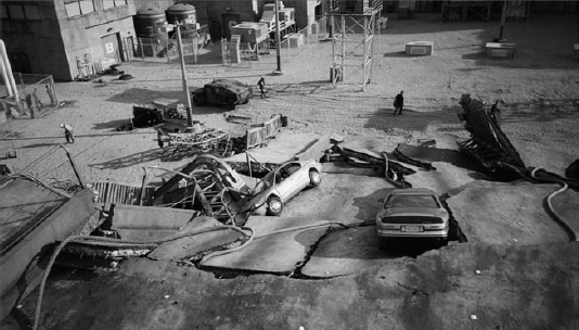
Deadlines are likely going to be very, very tight. Where standard architecture practice allows for months, in the film industry you'll have weeks. And where standard practice allows for weeks, you'll have days. Expect to work 12-hour days, 5 days a week and anywhere from 4 to 8 months for a major motion picture (with a break of a few months between productions). That's not 4 to 8 months for resolving design to documentation—it's for resolving concept to construction. And the detail to be resolved is going to have to be extraordinary, as shown in Figure 26.3.
FIGURE 26.3 Gritty realism in X-Men: The Last Stand
Construction can start from a napkin sketch in cases when the design is not too complicated. On more complicated projects, it's likely that you'll be working on site and very near to the construction and other production teams—as in the same building, down the hall, or possibly in the same war room. Some pieces of your design may be repetitive and contain parts that have to fit together with a high degree of precision. When this is the case, it's likely these pieces will be prefabricated via computerized numerical control (CNC) and then assembled on site. Fortunately, you can export other formats from Revit that quickly lend themselves to fabrication (such as *.sat or ACIS).
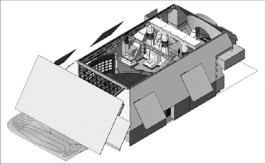
Bryan has worked on a number of third-act sets. Third-act sets are known for being large, complex, and/or highly themed because they'll be seen near the end of the movie and must leave a lasting impression. In the case of Watchmen, the Karnak set took months to create, and the Revit model was used to resolve issues ranging from design to camera angles to rigging for stunt work (Figure 26.4). Overall, remember that it's critical to stay a week or two ahead of the construction team because of the amount of lead time required by the set decorators after construction concludes.
FIGURE 26.4 Detail of glazing in Karnak

Even with all the early attention to detail during the design process, occasionally parts of sets will need to be pulled apart and rebuilt. But keep in mind this is extremely disruptive to the entire production process. The deadline has been set years in advance, and the budget is inflexible. The tolerance for rebuilds is becoming more unlikely now that 3D is becoming so common in the design process.
Scheduling
While quantities are important, in the middle of all this design iteration and visualization production, some standard architectural techniques may not translate into designing for film and stage. For example, it's unlikely that you'll be creating discrete schedules as you normally would. So rather than noting quantities on schedules, you'll tend to note them on sheets. This makes it simple and keeps as much information in one place as possible. You'll also indicate spacing—but again not the hard numbers.
Details
In the same way that traditional architectural schedules aren't used (but rather, quantities are noted in context with documentation), details are shown in the context of the elements being detailed. So, rather than segment your work into different groups (plans, elevations, sections, and so on), it's more likely that you'll be assembling your work in context, which is more like traditional architectural hand-drawn techniques. For example, being able to see both design intent and resolution at the same time is important. Plans, elevations, sections, and 3D views will likely be assembled together (not apart). This is particularly true as set builders can be given a lot of creative leeway, and you're often giving them enough information to get started. Prop builders, fabricators, and sculptors—they all love to have 3D representations! Taking an artist's sketch and putting it in context of the construction documents communicates the spirit of design intent (Figure 26.5).
FIGURE 26.5 Design intent and resolution on the same sheet
Dimensions
While we're discussing documentation, remember that dimensions in context with shaded views are better suited for resolving depth than mere hidden line views. Much of what you'll be designing in film and stage production involves curved, imaginative kinds of forms. These shapes aren't visualized well in black-and-white, 2D kinds of views. But if you change the views to shaded, curved elements are far more expressive. If you need to embellish 3D and perspective views, simply add the text and other notes outside the view once the views have been placed on the sheet.
Be sure to demonstrate finesse with regard to visualization that is suitable for communication as well as presentation—and sometimes these are different things. In other words, how you illustrate design intent comes in many styles and influences. But what's important is to be able to make deliberate design decisions while illustrating a certain aesthetic lack of resolution. Because so many people are going to influence the final product, you must visualize your work in a way that doesn't raise unnecessary objections while building consensus as quickly as possible.
Level of Detail
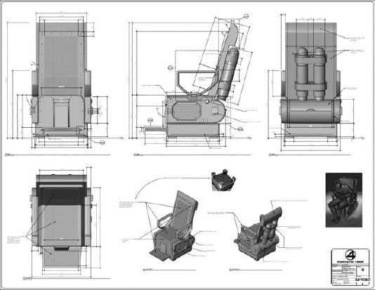
Level of detail is critical in the film and stage industries. Don't expect to model to the level of detail standard in architectural practice. In other words, you're not going to be able to model in 3D at a low level of detail and then document in 2D a greater level of detail. If the component calls for hardware, you'll probably model it. In this industry, geometric detail is vitally important. It'll be leveraged for documentation through visualization. What you model is what gets built—you're not going to be allowed to leave much, if anything, to guesswork or imagination (Figure 26.6).
FIGURE 26.6 Expect to model to a high level of detail.
Fabrication
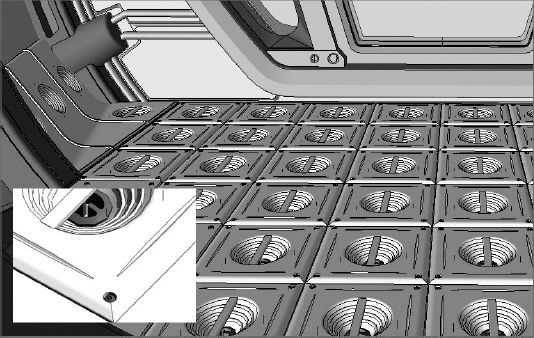
Fabrication is essential. CNC plays a large part in the set design industry and utilizes five-axis machining, laser cutting, and water cutting (which was used to create the lattice work in Figure 26.7 and the door panels in Figure 26.8). Speed and accuracy are huge benefits and provide unmatched precision for preassemblage.
FIGURE 26.7 CNC lattice work for pagoda from Fantastic Four: Rise of the Silver Surfer

FIGURE 26.8 CNC door panel detail for pagoda from Fantastic Four: Rise of the Silver Surfer

Five-axis tools usually mill high-density foam signboard if a more finished surface is required. If the surface needs to be less finished and a bit more porous, less dense Styrofoam is used (typically used for simulating concrete).
But for very tight, automotive-quality finishes, CNC machines are used to make the molds, which are then treaded and used as negatives for fiberglass casting, a process that was used to manufacture the Fantasticar, as shown in Figure 26.9. And although Revit wasn't used to model the Fantasticar, it was used to model the dashboard elements that were used in the car—and its garage.
FIGURE 26.9 Fantasticar garage and support elements from Fantastic Four: Rise of the Silver Surfer

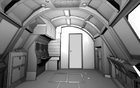
Geometry modeled in Revit will usually be taken to Rhino for unfolding a developable surface—like the airplane fuselage for Snakes on a Plane. But the structural ribs that were modeled in Revit were resolved by water cutting (Figure 26.10).
FIGURE 26.10 Cockpit interior of airplane fuselage from Snakes on a Plane
Construction
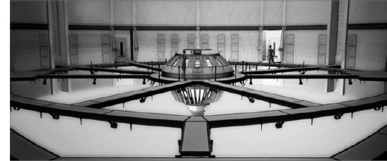
Some of the differences that you'll encounter in the film and stage industries compared to architecture will resonate when you get to construction. This is not to say that architectural projects aren't highly detailed—just that they're detailed differently. In film and stage production, you'll model not only what will be seen but in some cases what will not be seen. For example, when modeling, take into account the green screens beyond the actual sets as in Figure 26.11. Being able to accurately previsualize their size and locations during the design standpoint is important.
FIGURE 26.11 Green screens surround the Karnak set from Watchmen