
Understanding a BIM Workflow
Regardless of the design and production workflow you have established in the past, moving to BIM is going to be a change. In Chapter 1, “Introduction: The Basics of BIM,” we discussed some of those changes and tried to help define your place in the process of managing that change. Regardless of where you fall on the adoption curve, you'll still need some tools to help transition from your current workflow to one using Revit. To begin, we'll cover some of the core differences between a CAD-based system and a BIM-based one.
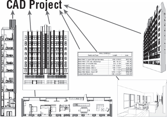
Moving to BIM is a shift in how designers and contractors approach the design and documentation process throughout the entire life cycle of the project, from concept to occupancy. In a traditional CAD-based workflow, represented in Figure 5.1, each view is drawn separately with no inherent relationship between drawings. In this type of production environment, the team creates plans, sections, elevations, schedules, and perspectives and must coordinate any changes between files manually.
In a BIM-based workflow, the team creates a 3D, parametric model and uses this model to automatically generate the drawings necessary for documentation. Plans, sections, elevations, schedules, and perspectives are all by-products of creating an embellished a BIM model, as shown in Figure 5.2. This enhanced documentation methodology not only allows for a highly coordinated drawing set, but also provides the basic model geometry necessary for analysis, such as daylighting studies, energy, material takeoffs, and so on.
FIGURE 5.1 A CAD-based workflow

Using Revit becomes more than a change in software; it becomes a change in workflow and methodology. To better address the impacts and nuances of this change in process, let's look at the existing paradigm. A traditional design and documentation workflow can be diagrammatically expressed, as shown in Figure 5.3.
FIGURE 5.3 The traditional method of design review

Design is a cyclical process and one of continual refinement. As you share ideas and coordinate information with the entire project team, you can make adjustments to your own portion of the project. A standard architectural project might go something like this:
- The architect draws a building design and shares this information with consultants.
- Various consultants, working separately, will reuse parts of the architect's drawings to create a new series of their own drawings specific to their discipline.
- The consultant's drawings will be shared with the architect, who will need to use them to further coordinate their own work. Portions that affect the architectural drawings such as building structure or mechanical ductwork are in a large portion redrawn within the architectural set.
- At a certain point in the project process, all of the drawings (typically in printed form only) are shared with a contractor or builder. The contractor disseminates the drawings to various subcontractors who will need to utilize their specialties to embellish the information in the original drawings.
- The contractor will create new sets of drawings with added detail related to the execution of the work but all based on the original set of documents.
With all of these separate teams making their own sets of drawings, a system of checks and balances is needed to ensure the information is communicated accurately and effectively. In our traditional model shown earlier, the subcontractors will send their drawings back to the contractor to verify the work. The contractor will create multiple copies of the drawings (based on the number of parties needed to review) and pass them to the architect. The architect will review their own set while giving the other copies to various consultants to do the same. All these changes will be manually transcribed to one set before being sent back to the contractor to be passed back to subcontractors for further revisions and clarifications.
This entire chain of manual information sharing has many opportunities for communication errors. Much of the information is redundantly reproduced as a way of error checking, which can just as easily create its own errors. If you can utilize the advantages inherent in a BIM-based method (Figure 5.4), you can eliminate many of the redundant efforts, improve communication, and focus more time on improving the design and expediting construction.
FIGURE 5.4 An integrated approach to design review
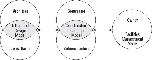
In an ideal BIM-based system, the following occurs:
- The architect and consultants would work together on a single building model. This might be one model or a model consisting of interconnected parts.
- After this model reaches a stage of refinement, it is passed on to the contractor and building team to further embellish with information specific to their trades and expertise.
- As they construct the physical building, the BIM model can be adjusted to reflect the changes that happen in the field.
- The revised model can then be shared with the owner and facilities operator. The model can contain the necessary product information about the systems installed to aid the owner's facility operator in maintaining the building. The model can also be used for future personnel moves or even building additions.
As various design specialists interact and create the building model (Figure 5.5), you can see how structure, mechanical, energy, daylight, and other factors inform design direction. You can also draw relationships between some of these elements that might not have been as obvious in a more traditional approach. Although some of these specialties (such as structure and mechanical) are historically separate systems, by integrating them into a single design model, you can see how they interact in relation to other systems with a building. Analysis such as daylighting can inform your building orientation and structure. Depending on your glazing, it can also affect your mechanical requirements (as solar gain). You can see some of these effects through a computational fluid dynamics (CFD) model (used to calculate airflow). Geographic information system (GIS) data will give you your relative location globally and allow you to see how much sunlight you will be receiving or what the local temperature swings will be during the course of a day. As you can see, all of these variables can easily affect building design.
As with any methodological change, you'll have success if you address all the factors. Project success happens on more than a financial or chronological level. It is also determined by a team's ability to replicate successful results. A difficult aspect of transitioning to BIM is predictability. Any system or method, even if it is inherently inefficient, is at some level successful if the system is predictable. If you can say that x effort + y time will yield z result, there is an established comfort level with that system even if it is an inefficient system. When you move to BIM, the system automatically becomes unpredictable because team members need to experience the new system to establish a comfort level with the given results. No longer does x effort + y time yield z; instead, the result is unknown.
FIGURE 5.5 The integrated design model

Eventually, you reach a point of temporary diminishing returns. The amount of effort you need to put into understanding the new process feels like it has begun to exceed the value you derive from the change, and happiness plateaus or slightly declines. At a point during this plateau, you're put in a position where you need to perform a task in a given amount of time using the new technology. It might be represented by needing to get a schematic-level design sent out to a contractor or create something as simple as a stair. Regardless, the process is a foreign one and by its nature is unpredictable in time. You'll be faced with a decision to forge ahead using an unpredictable method or revert to a more familiar yet inefficient process.
Here your path can split. By regressing to your previous process, you'll enjoy an immediate increase in happiness with the familiarity and predictability of the former method, but this will only level out and never reach any greater heights than it did before you contemplated the initial change. If you stay the course with the new process, happiness will decrease (and frustration increase) as you struggle with the change. However, as the new method eventually becomes more predictable and comfortable, your happiness can achieve greater value.
Although this might be an oversimplification of a process change, the core meaning is critical. Change can be challenging; however, to realize greater goals and adapt to an ever-changing environment both professionally and globally, you will need to rethink your process in order to achieve success. Moving to BIM is acknowledging a change in workflow and process—from abstraction to virtualization (Figure 5.6). As you transition from a traditional workflow to a BIM-based one, keep in mind the change in culture. It will help you to manage expectations, time, and team members' stress levels.
