Understanding Roof Modeling Methods
![]() In today's construction environment, roofs come in a great number of shapes and sizes. They can be as simple as a pitched shed roof or can involve complex double-curved surfaces or intersecting vaults. Once you understand the fundamental concepts, tools, and logic pertaining to roofs in Revit, you will be able to design almost any roof shape.
In today's construction environment, roofs come in a great number of shapes and sizes. They can be as simple as a pitched shed roof or can involve complex double-curved surfaces or intersecting vaults. Once you understand the fundamental concepts, tools, and logic pertaining to roofs in Revit, you will be able to design almost any roof shape.
Roofs are similar to floors and ceilings because they are sketch-based elements and can be defined in generic types or with specific material assemblies. You can also change a roof element from one type to another in the same manner as a floor or ceiling. A fundamental difference between floors and roofs is that a roof's thickness is generated above its referencing level, not below. You can also easily create slopes in roofs by defining slopes in the roof's sketch lines. In general, roofs in Revit can be constructed in four different ways: by footprint, by extrusion, by face, or modeled in-place. The following sections provide a closer look at these approaches and review their application to real-world scenarios.
Footprint Roofs
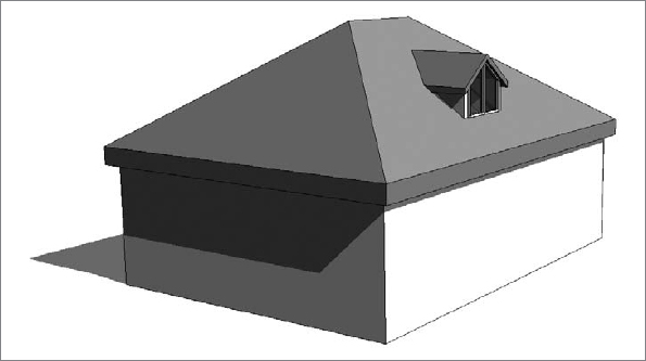
Use the roof by footprint method to create any standard roof that more or less follows the shape of the footprint of the building and is a simple combination of roof pitches (Figure 14.21).
FIGURE 14.21 A simple roof created using the roof by footprint method

These roofs are based on a sketched shape that you define in plan view at the soffit level and that can be edited at any time during the development of a project from plan and axon 3D views. The shape can be drawn as a simple loop of lines, using the Line tool, or can be created using the Pick Walls method that also should result in a closed loop of lines.
To guide you through the creation of a roof by footprint and explain some of the main principles and tools, here is a brief exercise demonstrating the steps:
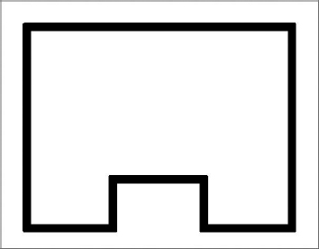
- In a new project, open a Level 1 plan view and create a building footprint similar to Figure 14.22. Make sure the height of the walls is set to Unconnected: 20-0 [6000 mm].
- Activate the Level 2 plan; then select the Home tab in the ribbon and click Roof
 Roof By Footprint.
 - From the Draw panel in the Modify | Create Roof Footprint tab, select the Pick Walls tool (this should be the default).
FIGURE 14.22 Sample building outline to be sketched on Level 1
- When you've chosen to create a roof by footprint, the Options Bar displays the following settings (change the Offset value to 1 −0 [300 mm]:

To define whether you want a sloped or flat roof, use the Defines Slope check box in the Options Bar. The Overhang parameter allows you to define the value of the roof overhang beyond the wall. When the Extend Into Wall (To Core) option is checked, the overhang is measured from the wall core. If the option is deselected, the overhang is measured from the exterior face of the wall.
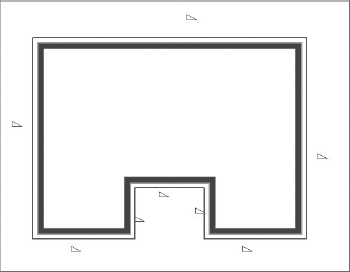
- After defining these settings, place your cursor over one of the walls (don't click), and using the Tab key, select all connected walls. Your display should look like Figure 14.23.
FIGURE 14.23 Roof sketch lines are automatically drawn after Tab-selecting the bounding walls, and they are offset from the walls by the value of the overhang as defined in the Options Bar.
- Select the two north–south walls within the alcove, open the Properties palette, and uncheck the Defines Slope parameter, as shown in Figure 14.24.
FIGURE 14.24 Uncheck the Defines Slope parameter for two of the roof's boundary lines.

- Click the Finish Edit Mode icon in the Mode panel of the ribbon. If you are prompted with the question, “Would you like to attach the highlighted walls to the roof?” click the Yes button. Activate a 3D view, and your roof should like the image in Figure 14.21.
If the shape of the roof doesn't correspond to your expectations, you can select the roof and select Edit Footprint from the Mode panel in the Modify | Roofs tab to return to Sketch mode, where you can edit lines, sketch new lines, pick new walls, or the modify the slope.
To change the slope definition or angle of individual portions of the roof while editing a roof's footprint, select the sketch line of the roof portion for which you wish to change the slope and toggle (check) the Defines Slope button in the Options Bar, toggle the Defines Slope parameter in the Properties palette, or right-click and choose Toggle Slope Defining. If you mistakenly made all roof sides with slope but wanted to make a flat roof, you can Tab-select all sketch lines that form the roof shape and clear the Defines Slope box in the Options Bar.
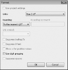
Roof slope can be measured in different ways: It can be set as an angle or percentage rise. All slope measuring options can be found in the Manage tab by selecting Project Units in the Project Settings panel and then selecting Slope to open the Format dialog box (see Figure 14.25). If the current slope value is not in units you wish to have (suppose it displays percentage but you want it to display an angle), change the slope units in the Format dialog box—you will not be able to do that while editing the roof slope. Setting it here means specifying the way you measure slopes for the entire project.
FIGURE 14.25 Format dialog box for slopes
Here are some of the important Instance Properties you should be aware of and need to set properly; all are found in the Properties palette shown in Figure 14.26.
FIGURE 14.26 Roof instance properties
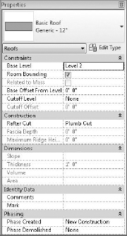
Base Level As in other Revit elements, this is the level at which the roof is placed. The roof moves with this level if the level changes height.
Room Bounding When this is checked, the roof geometry has an effect on calculating room area and volume.
Related to Mass This property is active only if a roof has been created with the roof by face method (Conceptual Mass tools).
Base Offset From Level This option lowers or elevates the base of the roof relative to the base level.
Cutoff Level Many roof shapes require a combination of several roofs on top of each other—for this you need to cut off the top of a lower roof to accommodate the creation of the next roof in the sequence. Figure 14.27 shows an excellent example of this technique.
FIGURE 14.27 The cutoff level applied to the main roof and a secondary roof built on top of the main roof using the cutoff level as a base

Cutoff Offset When the Cutoff tool is applied, the Cutoff Offset value also becomes active and allows you to set the cutoff distance from the level indicated in the Cutoff Level parameter.
Rafter Cut This defines the eave shape. You can select from Plumb Cut, Two Plumb Cut, or Two Plumb Square. When Two Plumb Square is selected, the Fascia Depth parameter is activated, and you can set the value for the depth.
Rafter or Truss With Rafter, the offset of the base is measured from the inside of the wall. If you choose Truss, the plate offset from the base is measured from the outside of the wall. Figure 14.28 illustrates the difference between the rafter and truss settings.
FIGURE 14.28 Rafter setting (left) and truss setting (right) for roofs

Roof by Extrusion
The roof by extrusion method is best applied for roof shapes that are generated by extrusion of a profile, such as sawtooth roofs, barrel vaults, and waveform roofs. Like the roof by footprint method, it is based on a sketch; however, the sketch that defines the shape of the roof is drawn in elevation or section view (not in plan view) and is then extruded along the plan of the building (see Figure 14.29).
FIGURE 14.29 An extruded spline-shaped roof

![]() Roofs by extrusion do not have an option to follow the building footprint, but that is often needed to accommodate the requirements of the design. To accomplish this, you can use the Vertical Opening tool to trim the edges of an extruded roof relative to the building outline.
Roofs by extrusion do not have an option to follow the building footprint, but that is often needed to accommodate the requirements of the design. To accomplish this, you can use the Vertical Opening tool to trim the edges of an extruded roof relative to the building outline.
To briefly explain the concept: You create a roof by extrusion by defining a profile in elevation or 3D that is then extruded above the building. The extrusion is usually based on a work plane that is not perpendicular to the building footprint, as shown in Figure 14.30. If the shape of the building is nonrectangular in footprint or the shape of the roof you want to create is not to be rectangular, this tool will let you carve geometry from the roof to match the footprint of the building or get any plan shape you need using a plan sketch.
FIGURE 14.30 Extruded roof created at an angle to the building geometry
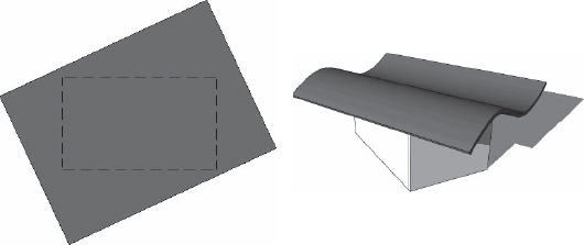
With sketch-based design, any closed loop of lines creates a positive shape, every loop inside it is negative, the next one inside that negative one will be positive, and so on. In Figure 14.31, a roof by extrusion was drawn at an angle to the underlying walls, but the final roof shape should be limited to a small offset from the walls. To clip the roof to the shape of the building footprint, the Vertical Opening tool was used to draw, in plan view of the roof, a negative shape that will remove the portions of the roof that extend beyond the walls.
FIGURE 14.31 The Vertical Opening tool with two sketch loops trims the roof to the inner loop

Roof In-Place
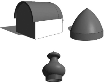
The roof in-place technique accommodates roof shapes that cannot be achieved with either of the previously mentioned methods. It is the usual way to model historic roof shapes or challenging roof geometries such as those illustrated in Figure 14.32. The figure shows a barrel roof with half dome (Extrusion + 1/2 Revolve), a dome roof (Revolve only or Revolve + Extrusion), and a traditional Russian onion dome (Revolve only).
FIGURE 14.32 Examples of modeled in-place roofs
To create an in-place roof, select the Home tab in the ribbon and click Component ![]() Model In-Place from the Build panel. Select Roofs from the Family Category list and click OK. While you remain in the In-Place Family editing mode, you can create any roof shape using solids and voids of extrusions, blends, revolves, sweeps, and swept blends (Figure 14.33). More advanced editing techniques are discussed later in this chapter, in the section “Advanced Shape Editing for Floors and Roofs.”
Model In-Place from the Build panel. Select Roofs from the Family Category list and click OK. While you remain in the In-Place Family editing mode, you can create any roof shape using solids and voids of extrusions, blends, revolves, sweeps, and swept blends (Figure 14.33). More advanced editing techniques are discussed later in this chapter, in the section “Advanced Shape Editing for Floors and Roofs.”
FIGURE 14.33 Organic-shaped roof created using the Swept Blend modeling technique

Roof By Face
The Roof By Face tool is to be used when you have created an in-place mass or loaded a mass family. These types of roofs are typically more integrated with the overall building geometry than the examples we've shown for in-place roofs. You can find more detailed information about using the roof by face method in Chapter 9.
Sloped Glazing
In Chapter 13, you learned that a curtain wall is just another wall type made out of panels and mullions organized in a grid system. Similarly, sloped glazing is just another type of a roof that has glass as material and mullions for divisions. Using sloped glazing, you can make roof lights and shed lights and use them to design simple framing structures.
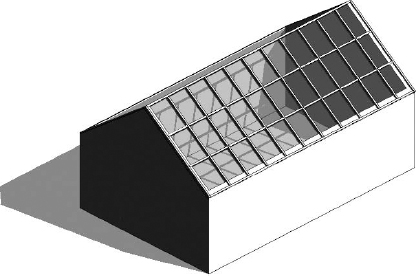
To create sloped glazing, make a simple pitched roof, select it, and use the Properties palette to change the type to Sloped Glazing. Once you have done that, activate a 3D view and use the Curtain Grid tool from the Build panel of the Home tab on the ribbon to start applying horizontal or vertical grids that define the panel sizes; then you can apply mullions using the Mullion tool in the Build panel. Figure 14.34 illustrates an example of a standard gable roof that has been converted to sloped glazing.
FIGURE 14.34 Sloped glazing is created by switching a standard roof to the Sloped Glazing type and assigning grids and mullions.
Slope Arrows
If your design calls for a sloped roof with an unusual footprint that does not easily lend itself to utilizing the Defines Slope property of boundary lines, slope arrows can be added within the sketch of the roof. First create the sketch lines to define the shape of a roof, but don't check Defines Slop in the Options Bar. Instead, choose the Slope Arrow tool from the Draw panel. Draw the slope arrow in the direction you want your roof to pitch. Select the arrow and in the Properties palette, you can set any of the parameters as shown in Figure 14.35. The Specify parameter can be set to either Height At Tail or Slope. If you choose Height At Tail, be sure to specify the Height Offset At Head parameter as the end result of the desired slope.
FIGURE 14.35 Defining the properties of a Slope Arrow added to an irregular footprint roof sketch

CREATING A DORMER STEP-BY-STEP
Roofs with dormers generally cause grief for architects, so we'll guide you through the creation of one:
- Create the base of a building, set up three levels, and create a Roof By Footprint with Defines Slope checked for all sides.
- Approximately in the position indicated below, on Level 2, create the four walls of a dormer. Set their height to a value that makes them extend above the roof. (For easier verification, create a cross-section through the dormer to check the height of the dormer walls and, if necessary, modify their height in the Element Properties so that they extend above the roof.)

- Using the Roof By Footprint tool, create a pitched roof on top of the dormer walls.
- If you switch to a side elevation view, you will notice that the dormer roof probably does not extend to meet the main roof, so you will need to use the Join/Unjoin Roof tool, located in the Modify tab in the Edit Geometry panel, to join the main roof and the dormer. Select the Join/Unjoin Roof tool, select the main roof as the target, and then select the edge of the dormer roof to extend.

- From the Opening panel on the Home tab, select Dormer. Now pick first the main roof, then the dormer roof, and then select the sides of the walls that define the dormer. Select the inside faces of the walls. Unlike most sketches, in this case you will not need to provide a closed loop of lines. Finish the dormer opening.

- The last thing to do is to go back to the section view you previously created and edit the elevation profile of the side walls to make sure they don't extend below or above the roofs. Note that you should not use the Top/Base Attach tool; instead, select the wall and use the Edit Profile tool available in the Mode panel of the Modify | Walls tab to edit its elevation profile and manually resketch the edge lines of the walls to get the triangular elevation profile as shown.

The correct dormer opening as shown cuts the roof in two directions.

As a final option, you can convert the front wall of the dormer to a storefront wall type or add a window.