Industry Examples
Having worked in the film and stage industries using Revit since 2003, Bryan has successfully managed a number of design challenges. The following are just a few production-related stories.
I, Robot
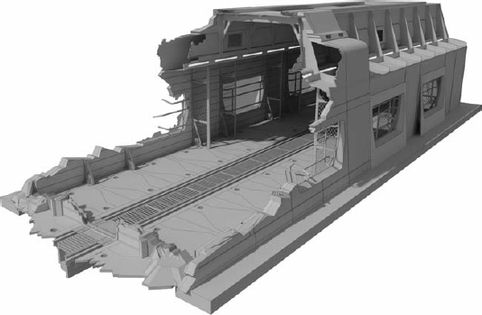
I, Robot was Bryan's first feature film and really quite special. After working for a number of years in set design at the scale of commercial production, it was trial by fire. The sets were much larger, as well as multistory, as shown in Figure 26.39.
Bryan had to take over from an architect, and in some cases, the drawings were hard to read. In other cases, one design view would not align with another view, and in this industry coordination is extremely important because of the short deadlines.
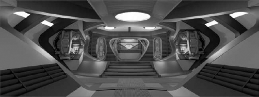
In Bryan's words, “Revit really saved the day.” Views were always consistent and always agreed with each other. The precision was always there, even considering the detail in the access walkway and platform surrounding the computer core (Figure 26.40). Revit was used to count the number of spider brackets used for the railings and other hardware.
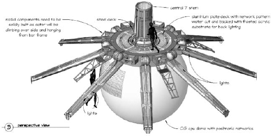
Ultimately, the VIKI brain that had been modeled in Revit for constructing the physical sets was leveraged for CGI work. This gave the CGI artists some great starting points (Figure 26.41). Again, precision was key.
FIGURE 26.39 Atrium walkway rendered in Revit: I, Robot

FIGURE 26.40 Platform and VIKI brain core, I, Robot
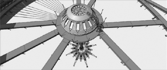
FIGURE 26.41 Shaded detail perspective of VIKI brain, I, Robot
Fantastic Four
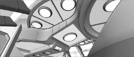
Fantastic Four was the next feature film that Bryan helped design in Revit. In this project, the level of detail increased because so many renderings were being done directly in Revit for this movie, starting with the interior of the space station (Figure 26.42).
FIGURE 26.42 Space station interior, Fantastic Four

Of course, these were the days of AccuRender—and many extra studio lights were placed in order to avoid the hard shadows that were common at the time. The shadows in AccuRender had hard edges and required a lot of artificial lights placed around the space, especially considering the detail and lighting of the ceiling (Figure 26.43). Fortunately, the implementation of Autodesk mental ray has improved the process.
FIGURE 26.43 Space station ceiling, Fantastic Four
The ceiling was challenging to model, according to Bryan, because there were so few straight lines. But he was able to do it with Revit using a lot of built-up solid and void relationships. The sweeps going along the edges of the ceiling and down to the floor were particularly challenging, as shown in Figure 26.44.
When you can't get the model just right, you have the geometry as context for documentation. This saves a lot of time over the back and forth compared to modeling in 3D, exporting, and then documenting in 2D.
FIGURE 26.44 Entry hall to space station, Fantastic Four
X-Men: The Last Stand
This project built on the challenges of the previous projects. Bryan soon found himself selected to design the third-act set (see the section “Lead Time and Production” earlier in this chapter). The island of Alcatraz was going to be third-act set and would be used for the big fight scene at the end of the X-Men film. It turned out to be an interesting challenge, because it involved a lot of both indoor and outdoor sets, such as the exterior Alcatraz set (Figure 26.45).
FIGURE 26.45 Alcatraz set, X-Men: The Last Stand, looking toward prison complex

Fortunately for the third-act set, you're likely to be given a bit more lead time. It's got to be detailed—and it's going to be used for the big finale. For X-Men, it also had to include a debris field that was supposed to suggest the ripped-apart end of the Golden Gate Bridge (Figure 26.46).
FIGURE 26.46 Alcatraz set, X-Men: The Last Stand, looking toward collapsed bridge structure
Snakes on a Plane
Originally, for Snakes on a Plane, actual pieces of aircraft fuselage were going to be used in context of the set pieces that remained to be built. So, the new challenge was integrating pieces of actual planes into Revit for context. But in the end, the art directors and set designers decided to rebuild the plane from scratch and simply gutted the existing plane for parts and set dressing (Figure 26.47).
FIGURE 26.47 Airplane section, Snakes on a Plane

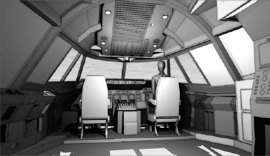
Some of the 3D shapes were a challenge. For instance, the fuselage consisted of complex shapes. But in the end, nearly the whole plane was designed in Revit, even the cockpit area (Figure 26.48).
FIGURE 26.48 Cockpit rendering, Snakes on a Plane
Fantastic Four: Rise of the Silver Surfer
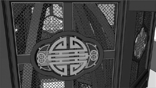
This project was rewarding—the people working on the project were great. According to the production designer, Revit helped “save the movie.” The set pieces, like the highly complex and detailed pagoda shown in Figure 26.49, required intricate structural elements and carefully cut screened panels.
In the case of the pagoda, full-sized sheets were printed and used as stencils for cutting the lofted, structural ribs. In other cases, CNC machines were used to cut out the door and panel pieces designed in Revit (Figure 26.50).
FIGURE 26.49 Exterior of the pagoda, Fantastic Four: Rise of the Silver Surfer
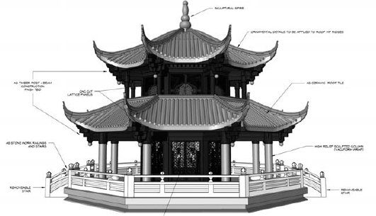
FIGURE 26.50 Pagoda upper screen detail, Fantastic Four: Rise of the Silver Surfer
Night at the Museum: Battle of the Smithsonian
For this movie, numerous set pieces were designed in Revit. But there was one particularly interesting challenge: a replica of the Wright Flyer, as shown in Figure 26.51, the world's first powered aircraft to achieve controlled, sustained flight. According to Bryan, there are companies that make very high quality replicas for museums and other displays. But in this case, though, the replica needed to be 85 percent smaller than the original. Oh, and the wings had to have proxy elements built of fiberglass so that the actor could walk on them during production.
FIGURE 26.51 Wright Flyer, Night at the Museum: Battle of the Smithsonian

While reviewing copies of drawings originally from the Smithsonian, Bryan wasn't sure that it could be done in Revit. The detail in the drawings was extraordinary. But once he began to visualize and understand the parts that made up the whole—the ribs, the frame, and the engine—it all became quite clear. In the end, according to Bryan, it was great fun modeling the Wright Flyer in Revit.
In fact, in addition to the air and space set, even smaller details like the afterburner for the F104 were modeled in Revit (Figure 26.52).
FIGURE 26.52 F104 Afterburner, Night at the Museum: Battle of the Smithsonian

Watchmen
Watchmen is a graphic novel (originally released as a limited 12-comic book series). It was created by writer Alan Moore, artist Dave Gibbons, and colorist John Higgins and published during 1986 and 1987. Although attempts to create a live-action film began shortly after the graphic novel's success, some deemed the complex narrative unfilmable.
Numerous production starts and stops continued until Warner Brothers brought in Zack Snyder (the director of 300) and principal photography began in 2007. Snyder even created his own storyboard sketches to fill in the action between the key frames of the novel. According to Bryan, “It was fantastic working for the director who creates his own version of storyboards. He has a very visual approach. I actually used the sketches for reference within the context of the design and construction documentation.”
Another detail that Bryan looked forward to during the Watchmen film and production was the opportunity to work with Alex McDowell, the production designer (www.imdb.com/name/nm0568273/). Bryan had long admired McDowell's work.
The Karnak set was the third-act set and would be extremely detailed. At the direction of McDowell, the bolt heads were modeled in Revit with chamfers (Figure 26.53).
Once again, phasing was used extensively to turn off and on large portions of the model to visualize the various stages of construction and production. The glazing system was also extensive.
Ultimately, the model was so complex that major portions of the model were done as large collections of nested families, as shown in Figure 26.54. This was done to manage the amount of highly detailed repetition.
FIGURE 26.53 Interior of Karnak, Watchmen
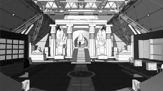
FIGURE 26.54 Complex structure family Karnak set, Watchmen

Creating individual families and then nesting them into a single, large family maintained design iteration. This large family assemblage was then loaded and placed into the project (Figure 26.55). Admittedly, families of this scale might not be a standard architecture best practice, as it would obviously affect scheduling. But the advantage to the exception in this case is pretty obvious. Rather than creating separate projects and linking them together, you're creating really large families and loading them into the project (Figure 26.56).
FIGURE 26.55 Support elements for Dr. Manhattan's lab, Watchmen
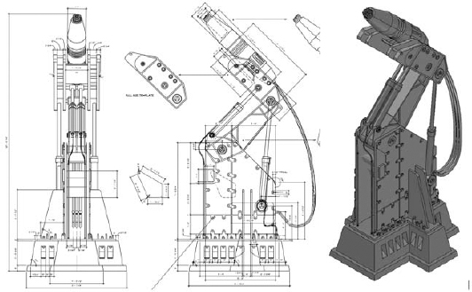
FIGURE 26.56 Tachyon corridor in Karnak, Watchmen
Design iteration could then be managed by opening the master family and then drilling down to get to the single nested family, as in Figure 26.57. Next, the nested families would be reloaded into the master family. Then, this master family would be reloaded into the project file, illustrated by the single cell in Figure 26.58.
FIGURE 26.57 Portion of Tachyon panel

FIGURE 26.58 Detail of nested Tachyon cell

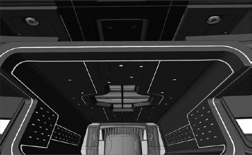
Tron Legacy
With Tron Legacy, Bryan used Revit to design the kind of spaces that many architects seldom get to experience in their entire careers. The End of the Line nightclub in Tron Legacy is just another example of his extraordinary work. Few walls were parallel; nearly all were slanted (Figure 26.59). Because of the multitude of chamfered edge conditions, Rhino was sparingly used to model a number of intersections (Bryan still laments that Revit can't create these chamfered shapes natively). SAT files from Rhino were imported into Revit families before being placed in the Revit project. But overall, the vast majority of the project was done in Revit—from design through documentation.
FIGURE 26.59 Interior of End of the Line bar

During the production process, significant design changes had to be accomplished in a very short time. In one case, the project had to be reduced to “85 percent of the previous design.” Well, you can't just scale down the set! The set designers and art director had to rethink the design, and using phasing, Bryan was able to visualize which portions of the set would be built and which could be stitched in virtually.
In Figure 26.60, the lighter, outer geometries indicate the portions of the set that could be computer generated, distinguishing them from the portions that could be physically and practically built. FBX exporting from Revit has been a huge improvement in tightening the distinction between the physical and the digital. What we're seeing, suggests Bryan, is “more and more digital agility between the designers, builders, and visual effects artists.”
FIGURE 26.60 Lighter, outer geometry indicates computer-generated portions of the set

It was times like this that the scheduling features of Revit were invaluable. Material takeoffs were completed in Revit for the structural steel (by gauge) because so many custom elements had to be built.
According to Bryan, set design represented a well-honed design–build environment. The art directors and set designers were on site and nearly side by side with the construction crews. Information was delivered just in time. Using 3D was essential to communicating with everyone involved (Figure 26.61).
FIGURE 26.61 Blue screens beyond the construction of the physical set

Contextual documentation was the only way to communicate as much information as efficiently as possible. As much information is shown on the sheet as possible in order to avoid waiting for numerous sheets to be delivered to the construction crews. As you can see in Figure 26.62, the simultaneous slanted and curved nature of the design would make communicating the project in 2D impractical. But even when you can model in 3D, you still need to clearly dimension and document—and it's very important to have both! According to Bryan, Revit excels in both areas.
FIGURE 26.62 Slanted and curved walls

Real-time, shaded views were still used extensively to indicate different materials and finishes. Figure 26.63 illustrates the reveals in the walls and ceilings that would be used for lighting and lighting channels. But the shaded views also helped quickly communicate what the camera would see long before actual set construction was complete.
FIGURE 26.63 Lighting reveals in the walls and ceiling
For more finished renderings, Bryan wanted to communicate materials with a more muted finish. But reflectivity and lighting was essential. The technique that he used was unique and elegant. Three views were exported from Revit: a rendered view, a real-time view with ambient lighting (no edges), and a hidden-line view.
These three views were composited in a photo-editing tool, where Bryan had control over the transparency of each image. The result allowed shadows and transparency, while accentuating the edges and providing textured, gritty surfaces. Figure 26.64 shows the results: a polished, yet hand-illustrated, look and feel—almost a graphic novel artistic sensibility.
So what was one of the high points of the entire project? After the production wrapped, the talent and crew held a fantastic wrap party in the nightclub used in the movie!
FIGURE 26.64 Composited views of the End of the Line bar

Sucker Punch
With Rick Carter (www.imdb.com/name/nm0141437/) as the production designer, Bryan knew that the Sucker Punch project would be an amazing challenge. Among his other high-visibility projects, Carter received an Oscar for his work on Avatar. The director and screenwriter of the project was Zack Snyder, who was also the director of Watchmen (another award-winning project that Bryan had worked on). Bryan described the design-to-construction process as “all over the place—but in a good way!”
Sucker Punch is about a young girl who has been locked away in a mental institution by her stepfather. But rather than accept her fate, she envisions a fantasy world that is a parallel to her real one and uses these visions to plan her escape along with her fellow inmates. As a result, many of the set pieces needed to be reminiscent of both her real/institution and fantasy worlds.
Bryan worked on numerous sets for this film, including the B-25 bomber, the nurse station/lounge bar, the Japanese temple, and the train car.
The bomber set was done in two separate parts: one for the nose and another for the main fuselage. Revit was essential to the success of this project and was used from design through documentation. Revit was also used to help fabricate the steel ribs used as the structure (Figure 26.65). After the separate sections were modeled in Revit, they were laser-cut from sheet metal.
FIGURE 26.65 Structural ribs ready for laser cutting

Because the model had been designed and assembled in Revit before laser cutting (Figure 26.66), the team was able to determine that the actual dimension of a B-25 bomber would not be adequate for filming. Bryan explained: “The real interior was far too small for the scene. In the actual plane there's only enough room to crawl on hands and knees to the tail gunning section. We had to enlarge it quite a bit.”
FIGURE 26.66 Fuselage structure designed in Revit

The nurse's station had to double as the lounge set in the film. Since one set was meant to reference another, both were created in the same Revit file, and Bryan used phasing to show either set in context with the other. Figure 26.67 shows the nurse's station, with its brick façade and surrounding chain link.

In another Revit phase and scene from the film, the nurse's station is shown from the same position—this time as a period bar (Figure 26.68).
According to Bryan, Revit excels at creating highly illustrative documentation. A great example of this is the full-scale detailed section of the bar top (Figure 26.69). For these details, Bryan manually traced around the outer edge of the geometry with a hatch pattern in order to accentuate the edge for the construction crews, and he claims, “They really love these kinds of details.”
For the Japanese temple set, only a small portion was physically constructed—the rest was a digital extension. The Revit file (Figure 26.70) was used to explore different roof possibilities for the digital set for the temple designed in Revit.
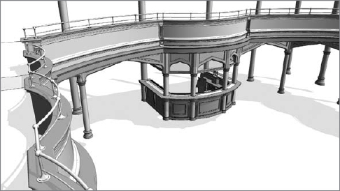
FIGURE 26.69 Detail section of lounge
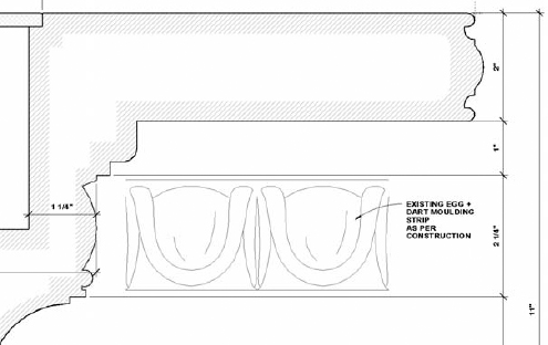
FIGURE 26.70 Japanese temple options

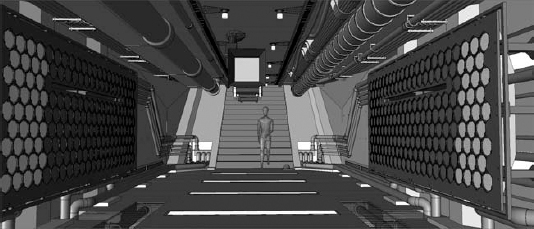
For the maglev (short for magnetic levitation) train portion, phasing played a major part in showing how the sets would need to be modified during the production of the film. In one phase, the roof is shown complete, whereas in another phase (Figure 26.71) the roof is shown blown open.
Once again, the rendering tools were used directly in Revit in order to visualize transparency, reflectivity, and artificial lighting (Figure 26.72).
FIGURE 26.71 Roof opening shown through phases
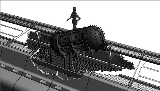
FIGURE 26.72 Matte renderings of the train's interior

Bryan used the same technique of merging both rendered and real-time images in order to give his images an illustrative, hand-drawn impression (Figure 26.73).
Without this technique, it would be difficult to visualize the level of detail required by the production designer as well as the construction teams. Small details, like the chamfered bolt heads around the lower edges of the train car and welded seams of the bulkhead door (Figure 26.74), would barely be noticed—yet they add an important look and feel to the image.
All of these visual and phasing techniques really pay off for the first train car. The level of detail is extraordinary. Voids are used extensively to communicate the front of the rail car being completely destroyed (Figure 26.75).
After Tron Legacy and Sucker Punch, Bryan completed work on Rise of the Apes and the next Mission Impossible film. But since these films are scheduled for release in the latter part of 2011 (after this book is published), we can't yet show his work on those projects. What's next? According to Bryan, it's likely to be with director Zack Snyder and production designer Alex McDowell on the next Superman movie or with the director of Tron Legacy, Joseph Kosinski (www.imdb.com/name/nm2676052/) on Oblivion.
We aren't sure how he's going to be able to choose between two great major motion pictures, but we know we can't wait to see the results!
FIGURE 26.73 Montage of real-time and rendered view
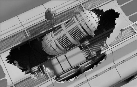
FIGURE 26.74 Detail of “exploded” roof looking into rail car