
Making Design Options for Design Iteration
Revit provides a set of tools for developing multiple design iterations in the context of one project. You can use these tools to explore alternative designs without having to save multiple independent versions of your model as you move in different directions. With Revit's design options, you create, evaluate, and mock up a wide range of options in the context of your project file. You're free to investigate multiple roof configurations or different entry canopies, explore various furniture and office layouts and stairs—quite literally anything that can be modeled. This functionality allows you to create views that show each option so the two designs can be compared.
Design options work in the following manner. First, you have a main model, which includes all the elements you've modeled that are fixed and not affected by the options you want to explore. The main model can be thought of as a backdrop or stage on which different options are displayed. Elements in the main model are always visible by default whereas design options—such as different furnishings for the interior or different canopies over an entrance—come and go, appearing and disappearing depending on what you're editing or viewing. Put another way, the main model includes everything else that's not in the design options.
You can make as many options as you need—there is no limit. You can create views for each option that only show that option displayed against the main model, and thus be able to place these views on a sheet in order to compare your designs. You can then present them to a client, to the project architect, or to other stakeholders in the design process. Once you settle on a design option, you accept it as the primary design solution going forward by adding it back to the main model. Doing so deletes all elements in the design option set that you won't use going forward. That is, some elements become embedded in the architecture, whereas others disappear forever.
Creating Design Options
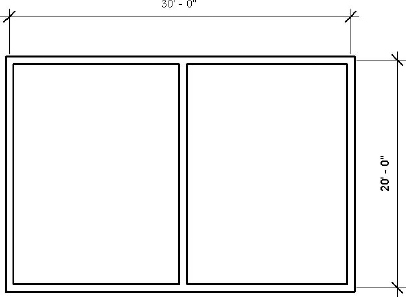
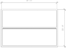
Let's start simple, establish the principle, and then add complexity later. Create four simple walls with a wall down the middle of the space, as shown in Figure 11.62.
FIGURE 11.62 Starting design options
We're going to configure this simple space into a design option that divides the space vertically in one option and horizontally in the other:
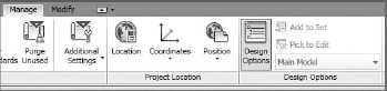
- Select the Manage tab to initiate design options. Then select the Design Options panel (Figure 11.63).
FIGURE 11.63 Design Options panel
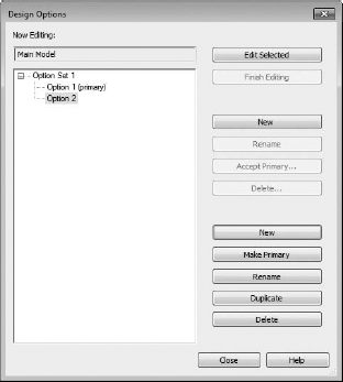
- Create a new option set (which will automatically create one design option) and then create another option, as shown in Figure 11.64. Click Close to dismiss the dialog box.
FIGURE 11.64 Creating an option set and two options
Now that you've started design options, everything in the project (which, admittedly isn't a lot) is now in the main model. Let's start adding elements to one of the two options.
- In a process that might at first to appear to be a bit confusing, select the center vertical wall and add it to Option Set 1/Option 1 (Figure 11.65).
FIGURE 11.65 Adding elements to option sets

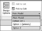
- You'll do this by selecting the wall, which you notice will immediately initiate the Modify | Walls tab. But you can get around this limitation by simply reselecting the Manage tab (that was just visible a moment ago before you selected the middle wall). Now select the Add To Set option and add the wall to the first option set but not the second one, as shown in Figure 11.66.
FIGURE 11.66 Selecting the option
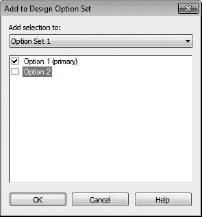
An alternative approach is to highlight the elements and use the Design Options drop-down list on the status bar at the bottom (Figure 11.67). Doing so opens the Add To Design Option Set dialog box you just saw in Figure 11.66. Both options provide the same result; which you choose depends on the workflow you feel is faster.
FIGURE 11.67 Adding elements to an option set using the status bar

You can also add elements to a specific design option set by selecting the option from the Design Options panel (Figure 11.68).
FIGURE 11.68 Another way to select and edit Design Options
Note that when the elements are added to the option set, they immediately become unselectable within the main model.
Editing Design Options
Selecting a design option to edit allows you enter a special mode called Edit Option mode. In this mode, you can add elements from outside the option set or create them from within the option set. The elements that are not inside this option set turn light gray, indicating that they are not editable. Now you can add another wall as shown in Figure 11.69.
To enter Edit Option mode, select the design option you wish to edit from the drop-down menu on the Design Options panel of the Manage tab, or use the drop-down menu from the status bar. You can then add, modify, or remove elements that are in the option set.
Viewing and Scheduling Design Options
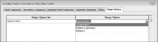
You'll notice that whenever you switch between Option 1 and Option 2, the view automatically changes to show the option that you've selected. Initiating design options automatically creates a new tab in the Visibility/Graphic Overrides dialog box. By default, the Design Options panel shows Automatic (Figure 11.70). This means that the primary design option (in this case, Option Set 1) will be shown in the view.
FIGURE 11.70 The Design Options panel displays Automatic.

The Design Options panel is available for any view, even for schedules. Selecting the Visibility Graphics settings in the view properties of a schedule filters the schedule according to the desired design option.
If you want to specify or lock a view to a particular design option, use the Visibility/Graphic Overrides dialog box (Figure 11.71).
FIGURE 11.71 Locking the view to a design option
Using the Visibility / Graphics override can be particularly useful for views that are being placed on sheets. For working views, it's fine to leave the view properties set to Automatic so that the view switches to actively show the desired design option.
Removing Design Options
As your project grows and begins to resolve more detail, it may be necessary to delete an option set, accept the primary design option, or delete a single design option. While some of these options might yield similar outcomes, there are important differences.
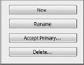
First, deleting an option deletes the option set and all of its associated options and any views that are specifically tied to that option set (via the Design Options panel discussed earlier). You delete an option set by selecting it in the Design Options panel and clicking the Delete button (Figure 11.72).
FIGURE 11.72 Select the option set and click Delete.
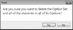
You'll see a warning indicating that you're about to delete all the geometry associated with the option set (see Figure 11.73). Click Yes.
FIGURE 11.73 Click Yes at this warning.
Additionally, any views that are associated with the option set will be deleted by default. However, you're given the option to deselect views that you want to retain, as shown in Figure 11.74.
FIGURE 11.74 You can deselect views that you want to retain.

Yes, you'll see a lot of warnings, but for good reason! All your related geometry, plans, elevations, sections, schedules, 3D views, and so on are about to be deleted. You do have the option to keep the views, but they'll only show what's left in the main model. The main model may or may not technically exist. That's because if you have only one option set in your project, then design options will no longer exist. There's no distinction between the main model and anything else.
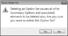
Accepting the primary design option ultimately removes the option set, but it also retains the geometry associated with the primary option, as shown in Figure 11.75.
FIGURE 11.75 Delete Option Set warning
You accept the primary design option by selecting the desired option set and then clicking the Accept Primary button in the Design Options panel. Accepting the primary option also deletes any of the other options associated with the option set. The design option set is removed and all of the geometry associated with the primary option is moved into the main model.
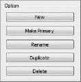
Finally, you can delete a single design option within an option set. However, you cannot delete a primary option—you'll first have to assign a new option as primary. To do so, select the desired option and then click the Make Primary button, as shown in Figure 11.76. Once you do, you can delete the former primary option.
FIGURE 11.76 Click the Make Primary button.
Just remember that all of the previous warnings will apply. Deleting a design option set will delete all the geometry and associated views.
![]() Real World Scenario: PUTTING IT ALL TOGETHER
Real World Scenario: PUTTING IT ALL TOGETHER
Now it's time to bring it all together—phasing, groups, and design options. Let's create a tenant finish package in two phases. The first phase will resolve construction on one side of the space, and then we'll turn to the other side of the space to complete the renovation. We'll also rely on groups for collections of components. Finally, we'll create a design option for the second space. Ultimately, you need to visualize the exercise in plan, perspective, and schedule.
Here's the existing condition of the space from the previous exercise. If you haven't created the file to this point, download that file to get started. Before you create your facsimile, remember that this will be the existing condition. So rather than create the existing walls and then change their phase, let's start by duplicating a view and changing the view of that phase so that the walls and other content are already on the existing phase.
Duplicate Level 1 and name the duplicate LEVEL 1, EXISTING, as shown here:
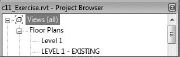
Then click inside the view to activate the view's properties; make sure that the phase is set to Existing.
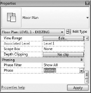
EXISTING PLAN
Leave the phase filter set to Show All for now. Don't be concerned that the elevation tags have disappeared in the view. View tags are also phase aware, and they're in the New Construction phase. The overall space is 80¢ ′ 80¢. We've also added some exterior dimensions as a reference. The finished exterior plan is shown here:

As you can see, the finished existing space is really two areas. In this scenario, the tenant in the lower-left space is expanding and will be taking over the upper space.
The idea is that we're going to demolish the space in stages. We don't want to upset the existing tenants to complete the phased work.
PHASE ONE: DEMOLITION
Some of the existing walls will remain. But you don't want to demolish them in this view. That's because the demolition should take place at the start of New Construction. But there's going to be two construction phases (so there will also be two demolition phases). If you haven't created those two phases, do so now, as shown here:

Now duplicate Level 1 again and rename as shown here. This will be the view that contains the demolition.

Now go to that view and be sure to change the phase and phase filter, as shown here:

Now demolish the walls as shown here. You don't have to demolish the doors if you demolish the walls that host them.

Now add the new elements. First, replace a portion of the walls around the upper-left spaces with storefront. Since the new storefront is proposed and the interior walls exist, this action will automatically demolish the openings. The graphic shown here is a perspective of the work so far. Recall that we've shaded the existing walls so that they'll stand out more from the proposed walls and that the demolished walls are in shown in red.
First, duplicate Level 1 and rename as shown here:
Make sure that the phase and phase filter are set as shown here. This view will only show the existing elements that remain after demolition and the proposed content.
Now start adding furniture to the space. You'll add a reception area and other office furniture. Add desks, tables, shelving, and chairs, as shown here:

Now start adding open office furniture. But group the assembly before you start copying through the office space.

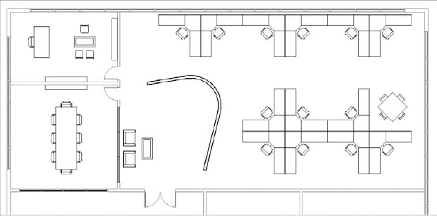
The graphic shown here is the completed space in a plan view:
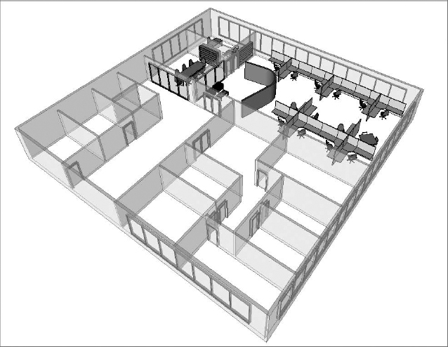
The graphic shown next is the space in a perspective view. Note that the demolished walls are not being shown. To give some graphic clarity and allow you to see through the context of the existing walls, we've temporarily set the transparency value of the existing material (in the phase properties) to 50%.
PHASE 2: DEMOLITION
Start by duplicating Level 1. Then rename the view to LEVEL 1, PHASE 2 DEMOLITION and set the phase and phase filters as shown here:
![]()
Now demolish the existing walls as shown here. Note that you'll have to split the long wall between Phase 1 Proposed and Phase 2 Proposed in order to allow only a portion of the wall to be demolished.

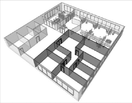
The graphic shown here is a perspective view showing the proposed demolition for the second phase. Don't be confused by the proposed content from the previous phase showing as existing. This is correct, since that content is now considered existing when seen through the lens of the second phase.
Now you'll duplicate the view again for the start of proposed work. Duplicate Level 1 and rename it to LEVEL 1, PHASE 2 PROPOSED. Set the phase and phase filter as shown here:
![]()
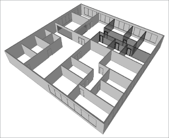
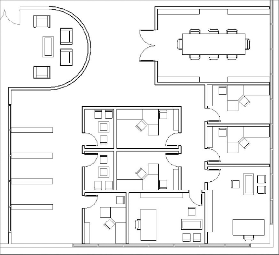
Start working in your new plan view, adding proposed elements as shown. Don't worry about getting the design right—just get the idea right. Here's the plan view:
Just remember, adding elements in the view with the appropriate phase and phase filter settings is the easiest way to avoid confusion. Here's a perspective of the same view:

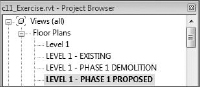
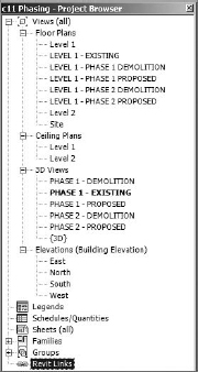
Now that you're finished with the demolition and proposed work in both phases, take a moment to set up a perspective view and then duplicate it three more times. Each of the views will show each phase sequence. Your Project Browser should look similar to this:
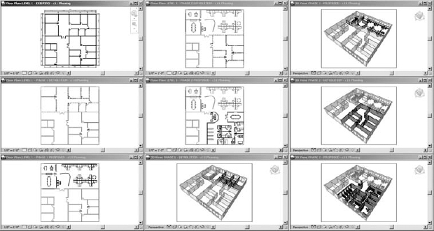
Except for the existing perspective view, here are all the tiled views thus far:
SCHEDULING
Now let's create a schedule for walls that will quantify demolition for each phase. As a side note, we believe it would be helpful to be able to create multicategory schedules that would allow both host and component categories to be scheduled at the same time—for example, you could schedule demolition for both walls and doors in the same demolition schedule. But this is not presently possible. So we'll create the schedules individually.
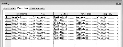
First, there's no phase filter to show only demolished elements. You'll need to create this filter, as shown here:
You can visually confirm what the filter will show by applying it to a working view.
Start by creating a schedule for walls that are being demolished by volume. You also need to estimate the cost of disposal for each phase. Create the schedule as shown here:

The following graphic shows the schedule fields that you'll need to create. You'll only be able to select the Type and Volume fields from the Available Fields selection.

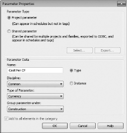
You'll also need to create a project parameter for the cost per unit volume (CF) per wall type. Click Add Parameter and fill out the resulting dialog box as shown here. Choose Type Parameter because you want to be able to add one value per wall type, not per each instance.
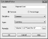
You'll need to add a calculated value in order to multiply the demolished units' volume by the cost per units and get the total. We've divided the Volume value by 1 in order to keep the units consistent, as shown here:
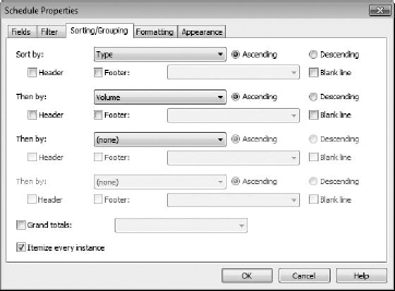
The next tab, Sorting/Grouping, should match the settings shown here:
Choose the Formatting tab and select Disposal Cost. Be sure to check the Calculate Totals box.

Now click the Format button for the Disposal Cost calculated value. Clear the Use Project Settings check box and change the unit symbol to $. Click OK.

When you're done, click OK to finish the schedule. The schedule will appear displaying the following values. Your schedule will not be exactly the same because the amount of demolition will vary between this example project and your project.

For the Phase 2 demolition schedule, don't start over. Duplicate the previously created schedule and just change the phase in the Properties palette, as shown here:

All that's left is to assemble the views on sheets. We'll only need to use two sheets. Each sheet will show a combined Phase 1 Demolition and Proposed views (plans, perspective, and schedules).
DESIGN OPTIONS
Everything looks great, but as to be expected, you need to show another option for Phase 2. This is easily done!
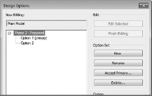
First, create a new design option set and two options, as shown here. Notice that we've renamed the set for clarity.

Here's a great tip. To isolate what you need to assign to Option 1, set the phase filter to Show New Elements. This will turn off any existing conditions from the previous phase.
Now select everything in the view, return to the Manage tab, and click Add To Set. Deselect Option 2, as shown here, and click OK. This will add everything to the Option 1 (primary) design option. Then set the phase filter back to Show Previous + New.

Now duplicate LEVEL 1 - PHASE 2 PROPOSED, and rename it to LEVEL 1 - PHASE 2 PROPOSED - OPTION 2. This will be your working view for the second design option.
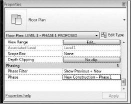
Next, set the view properties to show the second option:

Now make Option 2 active and create another design iteration, as shown here:

Now place this design option on the sheet next to the Phase 2 demolition and first option. You can also duplicate the perspective view of the first option; remember to change its Visibility Graphics to show Option 2:

If you'd like to download the file used in this example, you can find it in the Chapter 11 folder at this book's web page; the file is called c11_Exercise.rvt.