
Using Phasing to Apply the Element of Time
Phasing is Revit's method of allowing you to add the element of time to objects in your project. It's easy to think of an architectural design in terms of what something is, where something is, and how it will be assembled. Phasing adds the dimension of “when” something is, which is incredibly useful and powerful.
Phases are most useful for doing the kinds of tasks that require you to show when elements are being introduced into your design. But a few words of caution and clarification: we don't recommend using extensive phasing to simulate construction sequencing, or “4D.” It might seem like a great idea at first, but ultimately it'll break your model and lead to a lot of confusion across your project team.
The reasons for this are threefold. First, using phasing to illustrate construction sequencing will not allow you to use phasing for its intended use. So if you need to show stages of existing, demolition, new construction, and so on, you'll find yourself having to work around sequences of Week 1, Week 2, Week 3, and so on. You will have traded more functionality in one area for limited functionality in another area.
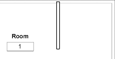
The second reason is that it will break connections between elements that are normally joined. For example, in Figure 11.1 two walls intersect that belong to the same phase. The fact that they are graphically and geometrically joined is the desired condition.
FIGURE 11.1 Wall joins in the same phase

But when walls are not from the same phase, their join condition may not clean up as intended, as shown in Figure 11.2. This can create a lot of tedious cleanup that probably isn't the best use of your time.
FIGURE 11.2 Joins across different phases may not always clean up as intended.
Finally, the best reason not to use phasing as a construction sequencing tool is that there's a better way that allows elements of various sequence properties to be scheduled, viewed, and even color-coded based on the sequence value that you define: project parameters.
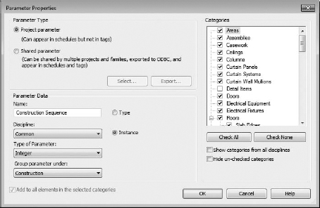
By using project parameters, you're able to create and assign an instance parameter value to everything in your project that you'd want to assign a construction sequence, as shown in Figure 11.3.
FIGURE 11.3 Creating a construction sequence instance parameter for project geometry
Once you've created this instance parameter, you'll be able to create view filters and filter rules that override the default condition of an object based on your parameter, as shown in Figure 11.4. Each Construction Week value is being given its own rule.
Combined with visibility and graphic overrides, you're able to create a filter that modifies the graphics based on a parameter, as shown in Figure 11.5.
The result is being able to modify the graphics of a view to illustrate some metadata about the objects in a far more flexible and predictable way than mere phasing, as shown in Figure 11.6. The other benefit is that this technique is not limited to views of geometry. View filters can be applied to any view, including schedules, which will allow you to group and filter schedules based on your unique project parameter.
FIGURE 11.4 Applying filters by parameter

FIGURE 11.5 View filters and graphic overrides settings

FIGURE 11.6 Using parameters and view filters to override graphics

Now that you understand a better way to create sequencing in Revit using parameters and filters, we'll discuss how phasing is best used.
What Can Be Phased?
At a high level, only three types of elements can be associated with a phase in Revit: geometry, rooms, and views. Geometry is anything that you would use to build your design, like host components such as walls, floors, ceilings, and so on, as well as family components such as doors, windows, furniture, lighting, and so on. Once an element is placed in the project, the phase may be changed, as shown in Figure 11.7.
FIGURE 11.7 Changing the phase of geometry
Rooms are also given phase properties, but there is an important difference: the phase of a building geometry may be changed after placement. The phase of a room may not, as shown in Figure 11.8. If you want to change the phase of a room, you'll need to delete and re-create the room in the desired phase. You'll also find it faster to press Ctrl+X to cut the rooms from one view and then press Ctrl+V to paste them into a view of the desired phase.
FIGURE 11.8 The phase of a room may not be changed after placement.

The phase of an element when initially placed is often confusing to a new user, but it's quite simple: the phase of the view that you're placing the element into determines its phase, as shown in Figure 11.9. Again, this is not as critical for geometry, since the phase of a building element can be changed after placement. But there are occasions when you're placing a lot of elements that you intend to be in a particular phase, and you'll want to create a view with that phase as active. Then you can place the elements in that view and not worry about having to change them later.
However, a view's phase is critical when you're placing rooms since you can't modify the phase of a room after placement. So be sure to verify the phase of the view before placing rooms.
FIGURE 11.9 Changing the phase of a view

Phase Settings
Let's get into the details of phase settings. Once you understand what each of the dialog boxes does (and what it doesn't do), the rest of phasing becomes clear.
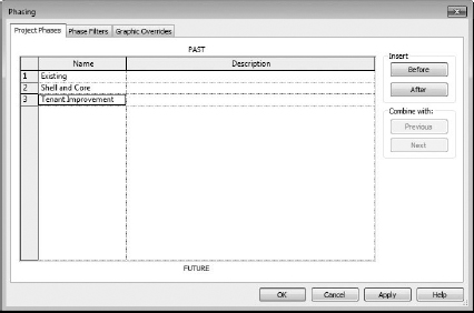
On the Manage tab, click the Phasing button, which will open the Phasing dialog box, shown in Figure 11.10. You'll notice that there are three tabs. The first tab is for your project phases.
FIGURE 11.10 The Phasing dialog box
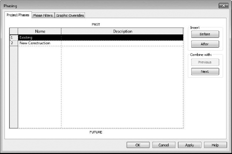
Right away, this is where people get confused, because they think that they need a phase for every different view that they'll be creating. And in the most common of phased projects, you'll have views to illustrate Existing, Demolition, and Proposed conditions. But since this dialog box only shows Existing and New Construction, new users will mistakenly create a new phase for Demolition.
If your project is a simple, three-phase project (like a tenant remodel showing three phases), this extra phase isn't necessary. Basically, the Project Phases tab is for determining when the geometry is being created (not demolished). When would you want to create more phases? When you need to create geometry in more than these two phases.
For example, think of a staged construction project that will happen in two new phases. In this scenario, you are designing with a start time for the building itself followed by another phase for interiors, allowing the owner to split funding for the project into two pots. In phase one, the building core and shell are built. In your second phase, tenant improvements occur. Your first phase is labeled “Shell and Core.” Your other phase is labeled “Tenant Improvement.” This phasing also gives the Revit-savvy contractor the ability to estimate the phase using the model to see what needs to be built and when.
Do you notice that we're still not creating a Demolition phase? Again, that's because the project phases allow you to set when geometry is being created—not demolished.
Create the two phases as just described (see Figure 11.11). We'll use them in a sample exercise in a moment. When you're creating phases, you might notice there's no Delete button. You don't want to delete any geometry put on a phase that is no longer useful in a project. What you can do is merge two phases using the Combine With button on the right.
FIGURE 11.11 Creating additional project phases
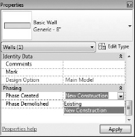
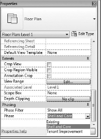
Once you've created these additional project phases, pick any project geometry and look at its instance parameters. You'll notice that it can be assigned to any one of these three phases, as shown in Figure 11.12.
FIGURE 11.12 Assigning available phases
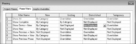
The next tab in the Phasing dialog box is Phase Filters (Figure 11.13). Seven predefined phases are listed.
Don't be concerned if the filter names seem a bit cryptic at first. What's really important is the four graphic conditions that can be overridden: New, Existing, Demolished, and Temporary. Concentrate on these views for the moment, and the filter names will begin to make sense.
Select any of the drop-downs, as shown in Figure 11.14. You'll notice that the phase filter can override the graphics in one of three ways:
- The object can be shown by its category settings or not overridden. It will display in the project just like it does by default.
- The object can be overridden. That means that you can define a graphic override for that object. We'll get into the graphic overrides in a moment.
- The object can simply not be displayed.
FIGURE 11.13 The Phase Filters tab, with seven predefined phases

FIGURE 11.14 Setting a filter override

Once you understand how each of the phase filters displays objects, phases can begin to make sense. For example, the Show Complete phase filter shows New and Existing elements by Category. But Existing and Temporary elements are not displayed at all. Use this setting when you want to show the model in a finished condition. To recap: things can be shown, not shown, or shown differently.
If there's any remaining confusion, it probably involves the naming convention of Show Previous + Demo. A better name might be Show Existing + Demolition but Existing is a bit misleading because this setting is showing the previous phase, which is not necessarily existing elements. They might be Temporary elements that need to be demolished. Therefore, Show Previous makes more sense.
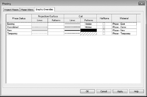
The Graphic Overrides tab is the final tab in the Phasing dialog box (Figure 11.15). This dialog box relates back to the “Overridden” assignment of the previous tab.
FIGURE 11.15 The Graphic Overrides tab

This tab allows you to override geometry in a few areas; the Lines and Patterns characteristics of Projection/Surface and Cut (which refers to the cut profile of objects cut). You also have the option to just halftone the element. Finally, you can assign a unique Material setting when rendering. Although this ability is helpful for illustrating rendering phase information, it can also be useful for rendering everything to a matte material, something we discuss in Chapter 15, “Conceptual Design and Sustainability.” As it is, phasing can show you where you are and where you're coming from, but not where you're going.
Geometry Phase
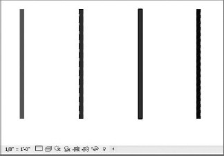
Here's a simple exercise to illustrate each of the phases in a single view. First, open a new project using a default template. Next, draw four walls in parallel and then open a 3D view (Figure 11.16).
By default, all of these walls have been created in the New Construction phase because the phase of the view is New Construction.
FIGURE 11.16 Four generic walls

Now, selecting each of the walls from left to right, associate them with each of the following phase settings:
Wall 1: Phase Created: Existing / Phase Demolished: None
Wall 2: Phase Created: Existing / Phase Demolished: New Construction
Wall 3: Phase Created: New Construction / Phase Demolished: New Construction
Wall 4: Phase Created: New Construction / Phase Demolished: New Construction
Figure 11.17 shows what you'll have when you're finished.
FIGURE 11.17 Default shaded overrides for phasing

Right away you'll notice that the Existing (not Demolished) and the Proposed (not Demolished) look similar. Graphically, this might not be enough to demonstrate the different phases, so let's change the graphic properties of this wall so it's visually more distinct.
Go to the Manage panel and select Phasing; then click the Graphic Overrides tab (Figure 11.18).
FIGURE 11.18 Default Graphic Overrides settings
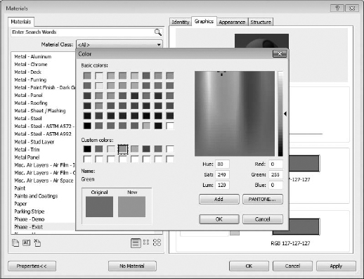
Next, select the option to open the Material setting for the Phase-Exist material (Figure 11.19). This opens the Materials dialog box highlighting the Phase-Exist material. Choose the Graphics tab.
FIGURE 11.19 Default shaded override for existing materials

This is the setting you want to change. Select the Shading option, and you'll be able to assign a different shading value. We're selecting the lime greenish color along the top row (Figure 11.20).
FIGURE 11.20 Overriding the Shading value
When you finish changing these settings, you'll have the result shown in Figure 11.21, with each phase shown distinctively within the view.
Now you can really graphically tell the phases apart. Once you settle on a color and graphic scheme, we recommend making this particular setting part of your default Revit template. That way, new users would be able to distinguish the phase of an object far more clearly, and the standard will be consistent throughout the office.
FIGURE 11.21 Finished shading values

View Phase
Now that we've talked about the phase properties of geometry, we'll cover the phase properties of views. Starting with the view from the previous example (the 3D view), select the View Properties from the Properties Panel, which should be active in the Properties palette, provided there are no elements highlighted (Figure 11.22).
FIGURE 11.22 Phase Filter options
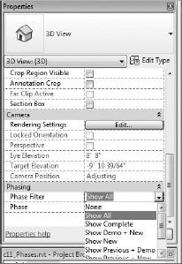
Applying each of these filters will help you understand the implications of how a filter will affect the properties of what will be shown in a view and how the object will be shown.
First, let's start by changing the phase to New Construction and setting the phase filter to Show All (Figure 11.23). Choosing these settings will show all the elements and override their graphics based on their construction phase and whether they're demolished. It also gives you a sense of all the elements as they exist in time.
FIGURE 11.23 Show All and New Construction

And although this is great for 3D views, where every phase has a distinct color, it's also wonderful for working in a plan, elevation, or section. To turn this graphic visibility on, change the Graphic Display setting to Shaded or Consistent Colors while working and you'll be able to clearly distinguish between objects in different phases, as shown in Figure 11.24.
FIGURE 11.24 Shaded plan view of phased elements
Now let's start moving through each of the sequences. But here's an important note: rather than sequentially moving through the various phase filters from top to bottom, let's move through a sequence that makes sequential sense.
Let's begin by going back to our 3D view and keeping the phase filter to Show All, but setting the phase back to Existing (Figure 11.25). This will only show the object created in the Existing phase—and their graphics are not overridden.
FIGURE 11.25 Existing phase only

Keep in mind that it's impossible to see anything that's proposed from this present Existing phase. That's because there's no way to see beyond the present phase and into future phases within Revit.
Now set the phase to New Construction and select the Show Previous + Demo option (Figure 11.26). This shows both existing walls (the walls from the previous phase). One of the walls is clearly being demolished. Keep in mind that the graphic overrides that are being applied are relative to what you'd be seeing through the lens of the New Construction phase.
FIGURE 11.26 Show Previous + Demo

Now select the Show Previous Phase option in the phase filter, as shown in Figure 11.27. The demolished elements are no longer shown.
FIGURE 11.27 Show Previous Phase

Now we'll move forward another moment in time and set the phase filter to Show Previous + New. This shows only the remaining elements (not any of the demolished content) from the present and previous view (Figure 11.28). It is not always necessary to click Apply each time you want to apply the settings you've just changed. Dragging your mouse outside the Properties palette has the same effect as clicking Apply.
FIGURE 11.28 Show Previous + New elements

This brings up another interesting point. Why not show the Existing to Remain as well as the Proposed and Proposed Temporary elements? Although you could also create a new phase filter, for this example, we'll change the settings of the Show Previous + New Graphic override settings (Figure 11.29). Choose the Manage tab and select Phases again. Choose the Phase Filters tab and, in the Show Previous + New row and the Temporary column, change the setting to Overridden.
FIGURE 11.29 Showing Existing and all New elements

Click OK to exit the dialog box. Figure 11.30 shows the result.
FIGURE 11.30 Existing to Remain, Proposed, and Temporarily Proposed elements

The next order of sequence will be to set the view to Show Demo + New, which would show demolished elements from the present and previous phase as well as any New elements from the present phase (see Figure 11.31).

This brings up another interesting point. If you want to show only the objects in the present phase (as well as demolition), then you'll want to modify settings on the Phase Filters tab, as shown in Figure 11.32. We don't know how common it is to show demolition from a previous phase without showing the existing from the same phase. That's why we're just changing an existing setting rather than creating a new phase filter.
FIGURE 11.32 Turning off the display of demolished elements from a previous phase
The result would be only the New and Temporary elements being shown in this view (Figure 11.33).
The next sequence, Show New, will show only the New elements in the present phase (Figure 11.34).
Now comes the final setting, Show Complete (see Figure 11.35). This only shows the existing elements that remain from the previous phase (after demolition) and the new elements that are being proposed (minus the temporary construction that has also been demolished).
FIGURE 11.33 Showing only New and Temporary elements

FIGURE 11.34 Showing only New elements

FIGURE 11.35 Showing finished conditions

This section gave you a good understanding of phasing and how to manipulate the phases for your particular project needs. You can download the finished example file from the book's companion web page in the Chapter 11 folder (www.sybex.com/go/masteringrevit2012). The filename is c11_Phases.rvt.