
Creating Schedules and Legends
![]() Schedules are lists of elements and element properties within the model. They itemize building objects such as walls, doors, and windows as well as calculate quantities, areas, and volumes. They also list document elements such as the number of sheets, keynotes, and so on. Schedules are yet another live way to view a Revit model. Once created, they are constantly kept up-to-date with any changes that occur to the model itself.
Schedules are lists of elements and element properties within the model. They itemize building objects such as walls, doors, and windows as well as calculate quantities, areas, and volumes. They also list document elements such as the number of sheets, keynotes, and so on. Schedules are yet another live way to view a Revit model. Once created, they are constantly kept up-to-date with any changes that occur to the model itself.
Legends are a way to graphically display building components, elements, or annotations used in your model. Legends can be created for displaying information such as door types, wall types, key plans, or general notes. Legends are unique in their behavior as a view because they are the one view in Revit that can be placed on multiple sheets. Building components in legends are not included in schedule quantities.
Schedules
In a project workflow, creating schedules of objects, areas, or quantities is usually one of the most laborious tasks for architects. When this process is performed manually, it can take a very long time and typically results in errors, requiring much checking and rechecking of the information. In Revit, all the elements have information about their properties defined within the model. You also have the option to add additional information or categories to any existing element. For example, doors have properties such as size, material, fire rating, cost, and so on. All of this information can be scheduled and quantified. Because the schedule is linked to the element within the model, making changes to the schedule itself makes changes to the element in the model, and vice versa.
Revit has several types of schedules, all of which can be accessed from the Create panel of the View tab. You can also create schedules by right-clicking on the Schedules/Quantities node in the Project Browser. There are five primary types of schedules you can create using Revit:
Schedule/Quantities This is the most commonly used schedule type in Revit. This schedule allows you to list and quantify all the element category types in Revit. You would use this type to create tabular views for doors, walls, windows, areas, rooms, and so on.
Material Takeoff This type of schedule can list all the materials and subcomponents of any Revit family category. You can use a material takeoff to schedule any material that is placed in a component or assembly. For example, you might want to know the volume of concrete within the model. Regardless of whether the concrete is in a wall or floor or column, you can configure the schedule to report the total amount of that material in the project.
Sheet List This schedule allows you to create a list of all the sheets in the project. In addition to the number and name of the sheet, you can include the current revision number, date, and revision description.
Note Block This schedule lists the notes that are applied to elements and assemblies in your project. You can also use a note block to list the annotation symbols (centerlines, north arrows) used in a project.
View List This schedule shows a list of all the views in the Project Browser and their properties. A view list is useful for managing your project because the schedule is a bidirectional view, which allows you to edit many view properties such as name, scale, and phase.
Each of these schedule types gives you the ability to select related element properties that you can mix and match to track elements within the model. When you create a new schedule, you must first select a category of objects to itemize (Figure 18.13).
FIGURE 18.13 Creating a new schedule

As you scroll through the list on the left, you can see a host of different schedule categories. If you need to schedule elements in categories other than architectural, Revit provides an option to access additional object categories. At the bottom-left corner of the New Schedule dialog box is the Show Categories From All Disciplines check box. Selecting this check box gives you the ability to schedule elements from MEP and Structural categories. This can be useful when you have those disciplines supplying Revit files to you and you are linking them to your architectural model.
While the most common schedules are based on a single object category, Revit also allows you the opportunity to create some schedules that span categories. The first option in the dialog box in Figure 18.13 is the <Multi-Category> schedule. You might want to schedule all the casework and furniture in a project simultaneously, or all the windows and doors if they are being ordered from the same manufacturer. A Multi-Category schedule allows you to combine a number of different categories into one schedule. One of the limits of this schedule type is that you cannot schedule host elements (walls, floors, ceilings, and so on) but only their materials and family components.
KEY SCHEDULES
As long as you don't need a multicategory schedule, there is a special kind of schedule in Revit that gives you the ability to populate a list of values before placing any actual objects in your model as well as manage these values from one location. Known as a key schedule, it can be selected when you first create a schedule. A common example of the use of a key schedule is to manage room finishes. In this use case, you create a key named Room Finish Type. You add the parameters Floor Finish, Base Finish, Wall Finish, and Ceiling Finish to the schedule. In the schedule, use the Add Row button to create room finish types. For example, you could create types for Executive Office, Standard Office, Service Corridor, and Rest Room.
The parameter Room Finish Type will then appear in the element properties of every room object. The parameters that are assigned to a schedule key can only be edited in the key schedule—not in the room properties. This might seem inconvenient; however, you can manage large numbers of objects with common parameters. For example, if the floor finish for all the rooms in your project that were assigned as an Executive Office type needed to change from carpet to ceramic tile, you would simply change the schedule key, and all instances of that room type would update.
After you select a category, you are presented with the Schedule Properties dialog box. This is the main interface by which you set and later modify any of the organizational or appearance characteristics of your schedules. The dialog box consists of five tabs: Fields, Filter, Sorting/Grouping, Formatting, and Appearance. Let's step through each of these tabs and examine how they affect the form and function of the schedule:
![]() Fields The Fields tab (Figure 18.14) lets you select the data that will appear in your schedule. The list of available fields on the left will vary based on the category you choose to schedule. If you've assigned any project parameters to those categories, they will be available here as well. Also notice the option Include Elements In Linked Files at the lower-left corner. Enabling this option will allow you to schedule across multiple files and can be a great tool for larger projects. The order of the fields you add to the Scheduled Fields list at the right side (top to bottom) determines the order of columns in your schedule from left to right.
Fields The Fields tab (Figure 18.14) lets you select the data that will appear in your schedule. The list of available fields on the left will vary based on the category you choose to schedule. If you've assigned any project parameters to those categories, they will be available here as well. Also notice the option Include Elements In Linked Files at the lower-left corner. Enabling this option will allow you to schedule across multiple files and can be a great tool for larger projects. The order of the fields you add to the Scheduled Fields list at the right side (top to bottom) determines the order of columns in your schedule from left to right.

Filter On the Filter tab (Figure 18.15), you can filter out the data you don't want to show in your schedule. Filters work like common database functions. For example, you can filter out all the sheets in a set that don't begin with the letter A. Or you can filter a material list so that it only shows items containing Concrete. Filters only operate on certain schedule fields. For instance, you can't apply a filter to the Family And Type field.

Sorting/Grouping The Sorting/Grouping tab (Figure 18.16) lets you control the order in which information is displayed and which elements control that order. For instance, if you are creating a sheet index, you can choose to sort by Sheet Number or Sheet Name, depending on how you'd like the information displayed. You can also decide whether you want to show every instance of an item or only a summary of object types by using the Itemize Every Instance check box at the bottom.
You can also determine how to summarize the reported information in your schedule. By checking the Footer options at any grouping or the Grand Totals option, you have the ability to show a title, count, totals, or all three. You must designate one or more fields to calculate totals in the Formatting tab to display results in grouping footers or the grand totals row.
FIGURE 18.16 The Sorting/Grouping tab

Formatting The Formatting tab (Figure 18.17) controls the display for each field and whether the field is visible on the schedule. It also controls other elements of the field, such as justification, display name, and orientation of the header. This tab also allows you to use the Calculate Totals check box for use with the footer or grand total options in the Sorting/Grouping tab. Note that you may also need to use the Calculate Totals option for certain numerical fields if you intend to deselect the Itemize Every Instance option in the Sorting/Grouping tab. For example, if you include the Area property of walls and choose not to itemize every instance, the area appears as a blank field in the schedule unless you check the Calculate Totals option.
FIGURE 18.17 The Formatting tab allows you to change unit formats and specify fields in which you need to calculate totals.

The Hidden Field option is also an important feature to help you customize your schedules. You can use this option when you need to include a field just for filtering or sorting but you don't want to see it in the schedule, such as a custom sorting parameter for drawing sheets. You can also select it when you want to use a field as the header of a group of elements in a schedule. For example, you may include the Family and Type fields, but you only want the family listed as a grouping header because you don't need to show the family name repeatedly in every row of your schedule.
Appearance The Appearance tab (Figure 18.18) controls the graphical aspects of the schedule, such as font size and style of text for each of the columns and headers in the schedule. It also allows you to turn the schedule grid lines on and off, and modify the line thickness for the grid and boundary lines. For revision schedules, you can also specify whether the schedule reads from top to bottom or from bottom to top.
Once you've established the fields and look of your schedule, clicking OK gives you a preliminary layout. The schedule's layout can be modified at any time during the project but gives you a basis from which to begin. To modify the schedule at any time, you can access any tab of the Schedule Properties dialog box from the five corresponding buttons in the Properties palette when the schedule view is active.
Schedules have their own special tab on the ribbon that is active when you are viewing the schedule outside of a sheet. This tab (Figure 18.19) allows you to select the properties, add and delete rows where the type of schedule allows, and show or hide columns within the schedule.
FIGURE 18.18 The Appearance tab

FIGURE 18.19 The Schedule tab in the ribbon.

Another key feature of this menu bar is the Highlight In Model button. This button allows you to select any element in the schedule and locate that element within the model. Let's say you want to locate a particular door from your door schedule. Select the respective row in the schedule and click the Highlight In Model button, and Revit will take you to a different view with that door highlighted. This technique can be a useful way to locate elements in the model, especially for larger models.
Now that you have an idea of the elements that compose a schedule, let's explore the workflow with two exercises. You will first create a simple wall schedule within the c18-Sample-Building.rvt project file and then create a Usable Area schedule based on the areas you defined earlier in this chapter.
MAKING A WALL SCHEDULE
In this exercise, you will create a schedule of building elements that are filtered to report only certain types of walls and simplified to show only a summary of each unique wall type within the project. Make sure you have the c18-Sample-Building.rvt file open.
- From the View tab in the ribbon, locate the Create tab and click Schedules and then Schedules/Quantities. The New Schedule dialog box opens.
- Choose Walls from the Category list and click OK.
- In the Fields tab, choose the following wall properties from the Available Fields list and add them to the Scheduled Fields list (in order):
- Function
- Family
- Type
- Area
- Switch to the Sorting/Grouping tab and set the first Sort By field to Family and check the Header and Blank Line options. Leave the Itemize Every Instance option checked for now.
- Click OK to close the dialog box and observe the amount of data that is available for this schedule. Let's refine the schedule even further.
- In the Properties palette, scroll down to find the Edit buttons related to the five tabs in the Schedule Properties dialog box. Click the button next to Filter. Set the first filter drop-down to Function equals Exterior.
- Switch to the Formatting tab and select the Function field from the list. Check the Hidden Field option and click OK to view the result in your schedule.
Note that now only the exterior walls are being listed. Walls with any other function property are not being itemized. Although the Function field is not shown, it must be included in the Scheduled Fields list to be used as a filter.
- From the Properties palette, click the Edit button in the Sorting/Grouping tab. Uncheck the Itemize Every Instance tab and check the Grand Totals option. From the Grand Totals drop-down list, choose Totals Only.
- Switch to the Formatting tab and select the Family field from the list. Check the Hidden Field option. Next, select the Area field, check the Calculate Totals option, and set the alignment to Right.
- Click OK to close the dialog box and observe the final modifications to your wall schedule (Figure 18.20).
FIGURE 18.20 The finished wall schedule displays a summary of elements.
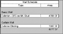
In this simple wall schedule exercise, you saw that a large amount of model data can be succinctly itemized and displayed using a combination of parameters within the elements. Only the exterior wall types were itemized, and the total area for each type was reported, including a grand total of all types.
MAKING AN AREA SCHEDULE
In our next exercise, you will create an area schedule specifically for the Usable Area scheme you established earlier in this chapter. The process is similar to that of creating a wall schedule.
To create the schedule, follow these steps:
- From the View tab in the ribbon, select Schedules and then Schedule/Quantities. From the Categories list, select the Area (Usable Area) schedule type and click OK.
- On the Fields tab, notice that the available fields in an area table are much more limited than they were in the Walls table in the previous exercise. For this schedule, you need only four fields: Level, Name, Area Type, and Area. Choose those from the Fields list on the left and, using the Add button, move them to the right.
Remember that the order of the fields in this list will determine the order of the columns in your final schedule. Use the Move Up and Move Down buttons as needed to order the list correctly.
- Next, choose the Sorting/Grouping tab. From the first pull-down, choose to sort by Level and check the Header and Footer boxes with the Totals Only option. Check the Itemize Every Instance option at the bottom. Also, select the option for Grand Totals and from the associated pull-down, choose Title And Totals.
- In this schedule, you want to make the areas read as they would in a spreadsheet—right-justified and totaled. Choose the Formatting tab and select Area from the list on the left. Change the justification to Right and check the Calculate Totals box. Select the Level field and check the Hidden Field box.
- Click OK to close the dialog box and observe your results (Figure 18.21). The areas placed on each level should be listed under a header and the total area should be calculated at the bottom of each grouped level. Finally, the sum of all areas is displayed as a grand total at the bottom of the schedule.
FIGURE 18.21 The final schedule is an organized list of areas according to their level.

ADDING SCHEDULES TO YOUR TEMPLATES
On a typical project, you will find that you will use the same schedules time and time again. Spend the time to make them consistent with your office's graphic standards, and add them to your office template. That way, you won't have to make them over and over again. As you add content to your model, the schedules will automatically populate, in effect filling themselves out.
You will find yourself making the same schedules for each and every project. Take the ones you find the most universal and make them a part of your default template. As you add content to the model, these will start to autopopulate.
If you have a schedule in another project and you want to add it to your project, there's no need to re-create it. Open both projects in the same instance of Revit. Go to the sheet that the schedule you want to copy is on. If it's not on a sheet, you'll need to place it on one. Then simply highlight it and copy it (press Ctrl+C) to the clipboard. In your destination project, go to any sheet and press Ctrl+V to paste it. Once the paste is finished, the schedule should be there with all the formatting from the previous project but with all the information from your current model.
CREATING A SHEET LIST
Using a Sheet List schedule, you can create a tabular view of sheets in your project—even including drawings being provided by consultants. This type of schedule allows you to create placeholders for sheets that are not yet created or will not be a part of your discipline's drawing set.
In the sample workflow, you have created area plans for the Usable Area scheme. Eventually, you may want to create another area scheme based on departmental spaces. You haven't created them yet, but you want to create your sheet list, including the area plans that you will create later. To do this, follow these steps:
- Select the Sheet List tool from the Schedules flyout in the View tab.
- The Sheet List Properties dialog box opens to the Fields tab. On this tab, select two fields from the categories on the left and move them to the column on the right. Select the Sheet Number and Sheet Name categories.
- On the Sorting/Grouping tab, choose to sort by Sheet Number and make sure the Itemize Every Instance check box is checked. Click OK to close the dialog box.
- To begin adding sheets to the sheet list, click the New button in the Rows panel. This will give you a row with the next sequential number based on the last number you entered. Change the sheet number in the new row to P101 and click the New button again. The next new row should be P102. Change the names of P101 and P102 to LEVEL 1 AREA PLAN and LEVEL 2 AREA PLAN, respectively.
You can continue populating the schedule in this way, adding any sheet names you need or plan to have in the presentation package. Next, you will begin to create a sheet directly from a row in the sheet list.
 Start by selecting the New Sheet button from the ribbon. This will give you a dialog box similar to Figure 18.22.
FIGURE 18.22 Converting a placeholder into a sheet

- Select the type of sheet border you'd like to use from the list at the top. Choose the C size sheet border for this exercise.
- Select P101 - LEVEL 1 AREA PLAN from the list of placeholder sheets and click OK.
This will create a sheet from the line item in the schedule using the same name and sheet number. The new sheet will appear under the Sheet node in the Project Browser with the correct number and name. You will begin to add views to this sheet later in this chapter.
Legends
![]() Legends are unique views in Revit as they are the only view type you can place on more than one sheet. They can become great tools for things like general notes, key plans, or any other view type that you will want to have consistent across several sheets. It's also important to note that anything you place inside a legend view—doors, walls, windows, and so on—will not appear or be counted in any schedules. Legend elements live outside of any quantities present in the model.
Legends are unique views in Revit as they are the only view type you can place on more than one sheet. They can become great tools for things like general notes, key plans, or any other view type that you will want to have consistent across several sheets. It's also important to note that anything you place inside a legend view—doors, walls, windows, and so on—will not appear or be counted in any schedules. Legend elements live outside of any quantities present in the model.
The Legend tool is located on the Create panel in the View tab. There are two types of legends you can create from this menu: a legend, which is a graphic display, or a keynote legend, which is a text-based schedule. Both legend types can be placed on multiple sheets, but for this exercise, you'll focus on the legend. The keynote legend will be handled in more detail in Chapter 19, “Annotating Your Design.”
As part of the sample workflow, you may want to present some of the wall types as part of your presentation package to demonstrate the Sound Transmission Class (STC) of the walls and the overall wall assembly. Since these wall types will be appearing on all the sheets where you are using them in plan, you'll make them using a legend.
To make a legend, choose the Legend button from the View tab under the Legends flyout. Creating a new legend is much like creating a new drafting view. You'll be presented with a New Legend View dialog box (Figure 18.23), where you can name the legend and set the scale. For this legend, name it WALL LEGEND and choose 1″ = 1′-0″ [1:10] for the scale.
FIGURE 18.23 Creating a legend

The legend you've created will look like a blank view. At this point, it's up to you to add content. The simplest type of legend would be adding notes such as plan or demolition notes that would appear in each of your floor plans. You could do this simply by using the Text tool and adding text within this legend view; however, in this example you want to add more than just text.
To add wall types or any other family to the legend view, expand the Families tree in the Project Browser and navigate to the Wall family. Expand this node and then expand the Basic Wall Node. Select the Interior – 4 7/8″ Partition (1-Hr) wall type and drag it into the view.
With the family inserted into the view, it will appear as a 3′ [1000 mm] long plan wall. Change your view's detail level from Coarse to Medium or Fine so you can see the detail within the wall. With that done, highlight the inserted wall and look at the Modify | Legend Components settings in the Options Bar (Figure 18.24).
FIGURE 18.24 Select a legend component to access its properties in the Options Bar.
![]()
This menu will be consistent for any of the family types you insert. The menu consists of three sections:
Family This drop-down menu allows you to select different family types and operates just like the Type Selector does for other elements within the model.
View The View option lets you change the type of view from Plan to Section.
Host Length This option changes the overall length (or in the case of sections, height) of the element selected.
Let's make some minor adjustments to the wall. Let's change View to Section and change Host Length to 1′-6″ [500 mm].
The wall now looks like a sectional element. By adding some simple text you can embellish the wall type to better explain the elements you're viewing (Figure 18.25).
FIGURE 18.25 Add other annotation to embellish the wall type section.
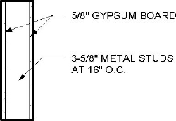
Continue the exercise by adding the Exterior - EIFS on Metal Stud wall type to the legend along with some additional text notes.