
Creating Complex Curtain Walls
Often at the early stages of design, as an architect or designer, you need to be able to model curtain wall systems that indicate design intent. These systems need to be flexible and robust enough to allow us to explore design iteration, but they also need to be useful enough downstream as your project moves from concept to design development and then on to fabrication.
In Revit Architecture you can build Concept Curtain Walls utilizing Revit conceptual massing tools. There are two potential workflows, and it's important to understand the differences. You can model your curtain wall system directly within the project environment from massing forms, or you can build it as a family within a conceptual design environment.
Project Environment You can build your forms directly within your project environment using the in-place massing tools. When constructing concept curtain walls through the In-Place Mass tool, the conceptual design environment does not have 3D reference planes and 3D levels.
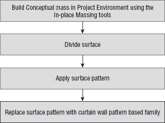
Conceptual Design Environment (CDE) You create your concept curtain wall designs in the Revit Conceptual Design Environment (CDE), which is a type of family editor. These forms reside outside the project environment. You can then reference these massing families into a project environment, allowing you to explore contextual relationships with the building form.

You start by designing your conceptual form that will represent the shape and form of the surface of the curtain wall. You are then able to subdivide the surface of this form using a grid system, referred to as a UV grid. As surfaces are not always planar (flat), a UVW coordinate system is used to plot location across the surface. This grid system automatically adjusts following the natural contours of a nonplanar surface or form. The UV grid is then used as a guide for patterning the surface. You can investigate how you might panelize the surface to make it constructible by applying a geometric pattern to the surface. This pattern provides a basic graphically representation of how the panel may look. These graphic patterns can then be replaced with parametric components that automatically conform to the divided surface.
Dividing the Surface
Let's take a look at the basic tools that will allow you to divide the surface of a conceptual form:
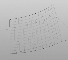
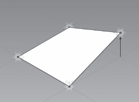
- Start by opening c13-Square-Panel.rfa from this book's companion web page. This file represents a simple conceptual shape for a curtain wall design (Figure 13.49).
FIGURE 13.49 Conceptual shape to be used as a basis for a complex curtain wall design

- Select the form and then click Divide Surface on the Modify | Form tab in the ribbon. This will divide the surface of the form and you will see horizontal and vertical grids displayed. This is the UV grid.
Note that you can control the display of the UV grid when it is selected (Figure 13.50). To modify the display, click the U Grid or V Grid button in the UV Grids And Intersects panel on the Modify | Divided Surface tab of the ribbon.
FIGURE 13.50 A surface of the conceptual form has been divided and the UV grid is displayed.
- Make sure UV grids are both displayed and the surface is selected. Notice how the Options Bar provides a number of settings for you to modify the divided surface. You can control the U grid and V grid by a number or with a specific distance. If you select the Number option, you can enter a number of divisions that will distribute evenly across the surface.
- Select Distance, which will allow you to enter a specific absolute distance between grids across the divided surface. Under the Distance setting, there is a drop-down menu that also allows you to specify a Maximum Distance or a Minimum Distance, which are similar to the constraints described earlier in this chapter for basic curtain walls. Make sure the surface is divided by Number, with a U grid of 10 and a V grid of 10.
- With the UV grid selected, you will see a 3D control (xyz axis arrows), and an icon appears in the center of the surface. Click the icon to enable the Configure UV Grid Layout command. The display will change (Figure 13.51) and you can now apply specific settings to control the UV grid even further. You have the ability to alter the rotation of the grid, the UV grid belt, and justification of the UV grids at the surface borders. These grid configuration parameters can also be found and modified in the Properties palette.
FIGURE 13.51 The UV grid can be configured by clicking the icon at the center of the surface.

- In the Properties palette, set the U Grid Rotation value to 45 degrees, and set the V Grid Rotation value to 45 degrees; then click Apply. Notice how the modified values are updated in the 3D view with the Configure UV Grid Layout command activated.
In the Configure UV Grid Layout mode (Figure 13.52), you will see a number of controls—all of which relate to parameters you can also access in the Properties palette. The arrow cross in the middle of the grid is the grid justification marker. You can drag it to any side, corner, or center of the grid, which will adjust the value of the Justification property of both U and V grids.
The belts represent the lines along the surface from which the distance between grids is measured. The distance is measured by chords, not curve lengths, and can be seen in the Properties palette as the Belt Measurement parameter for both U and V grids.
FIGURE 13.52 The UV grid can be modified directly or via the values in the Properties palette.

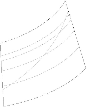
Dividing the Surface with Intersects
As you have seen in the previous exercise, the Divide Surface tool allows you to divide the surface of a form using the natural UVW grid of the surface. However, if you want to divide the surface with a customized grid pattern, you divide a surface by intersecting geometry. By using the Intersect feature, you can divide the surface based on the following:
- Intersecting levels, reference planes, and even lines drawn on a reference plane
- A mixture of U or V grids and intersects
Let's take a look at an example based on our previous file, which will demonstrate how you can use a series of defined reference planes to divide a surface.
- Start by opening the file c13-Square-Panel-Intersects.rfa from this book's companion web page.
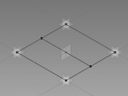
Notice that a series of reference lines have been drawn in the X plane; you will use these reference planes to divide the surface of the form.
- Select the surface and choose Divide Surface from the ribbon. Click the U Grid tool on the ribbon to disable the display of the U grids.
- With the surface still selected, click the Intersects button on the ribbon. Select all the reference planes in the X plane and then click the Finish icon in the Intersects panel on the ribbon. This will divide the surface based on where the reference planes intersect the surface of the form. Note that you could also choose Intersects
 Intersects List to choose named references such as levels or named reference planes instead of picking them in the model view.
 - Go to the Project Browser and open the 3D view named 3D surface to review the results (Figure 13.53).
FIGURE 13.53 The surface is divided by intersecting planes and lines.
Applying Patterns
Surface patterns allow you to quickly preview in a graphical manner how a panel will work across the surface of the form. As you are not working with complex geometry at this stage, the editing and adjustment to the design concept is quick. Revit provides a number of predefined patterns that are available from the Properties palette, and they can be applied to your divided surface. You will now apply a surface pattern to a form:
- Start by opening c13-Square-Panel-Pattern.rfa from this book's companion web page.
- With the UV grid on the form selected, you will notice in the Type Selector that the default empty pattern named _No Pattern is applied to the surface. Open the Type Selector and you will see that you can apply one of a number of predefined patterns to the surface. Click the Rectangle Checkerboard Pattern type to apply it to your surface (Figure 13.54).
- Experiment with the various predefined patterns and adjust the UV grid as required to play with the proportions of the patterns.
FIGURE 13.54 Surface with Rectangle Checkerboard Pattern applied

At any time, you can display both the underlying surface divisions along with the pattern display. With the grid selected, click the Surface button in the Surface Representation panel on the Modify | Divided Surface tab. This display should give you a better understanding of the relationship between the pattern definition and the spacing of the surface divisions.
Editing the Pattern Surface
There will be situations where you will want to edit and control the border conditions for pattern surfaces. Patterned surfaces may have border tiles that intersect the edge of a surface, and they may not end up as complete tiles. You can control the border tile conditions by setting them to Partial, Overhanging, or Empty in the Border Tile instance property of the patterned surface. You will now modify a conceptual curtain wall to examine how the different border conditions affect the surface.
- Start by opening c13-Square-Panel-Border.rfa from this book's companion web page.
- Select the surface and in the Properties palette, locate the Border Tile parameter under Constraints. Set the value to Empty and click Apply. Notice that the tiles at the borders are no longer visible, as shown in Figure 13.55.
- Next change the Border Tile parameter to Overhanging and click Apply. The border tiles will now show in their entirety, extending beyond the edge of the surface.
FIGURE 13.55 Border parameter set to Empty
Surface Representation
When editing a surface in the conceptual design environment, you have the option to choose how surface elements will be displayed. A number of options are available to you, allowing you to customize how you show or hide the various elements that make up a divided surface in a view. If you select either the U or V Grid icon, this will enable or disable the UV grid in the view. The Surface icon allows you to display the original surface, nodes, or grid lines. The Pattern icon allows you to hide or display the pattern lines or pattern fill applied to the surface. The Component icon allows you to hide or display the pattern component applied to the surface. If you decide to make any changes to the display using the Surface Representation tools, these changes will not carry through into the project environment. To globally show or hide surface elements you will have to alter this from the Visibility/Graphic Overrides dialog box.
In the Surface Representation panel, you will also notice a small arrow in the bottom-right corner. Clicking this arrow will open the Surface Presentation dialog box, where you will find additional display options for the surface, patterns, and components. You also have the ability to display nodes and override the surface material of the form. Let's practice controlling the surface representation of your form.
- Start by opening c13-Square-Panel-SurfaceRep.rfa from this book's companion web page.
- With the surface selected, go to the Surface Representation panel in the ribbon and click the arrow in the bottom-left corner to open the Surface Representation dialog box (Figure 13.56).
FIGURE 13.56 Use the Surface Representation dialog box to further customize the display of your form.

- On the Surface tab, enable Nodes if is not already enabled; this will display a node at each intersection of the UV grid, as shown in Figure 13.57.
FIGURE 13.57 Nodes are displayed at the intersection of the U grids and V grids.

Adding Definition
So far, you have created a surface, subdivided it, and applied a graphical representation to the form. You can now begin to add actual component geometry similar to mullions and panels. Note that although the underlying graphic pattern will remain, the component geometry will take precedence. To begin this process, you will create special curtain panel families using the Curtain Panel Pattern Based.rft or M_Curtain Panel Pattern Based.rft family template. This type of panel family can be applied to the divided surface to populate it with architectural components, adding realistic definition to your conceptual curtain wall surface.
BUILDING A PATTERN-BASED PANEL FAMILY
In the following exercise, you will build a simple rectangular panel and apply it to your divided surface.
- Click the Application menu, choose New Family, and select the Curtain Panel Pattern Based.rft family template.
Figure 13.58 shows the pattern-based curtain wall family template, which consists of a grid, a series of reference lines, and adaptive points. The grid is used to lay out the pattern of the panel. The adaptive points and reference lines act as a rig, defining the layout of the panel. You can construct solid and planar geometry within and around the reference lines to form the panel.
When a panel is applied to a divided surface, the points in the panel adapt to the UV grid and the panel will then flex accordingly. As a general rule, the grid pattern in your curtain panel family should match the pattern on the divided surface to which it is applied. For example, if you have applied a hexagonal pattern to your divided surface, make sure that the curtain panel family is also using a hexagonal pattern.
FIGURE 13.58 The rig in the pattern-based curtain panel family
- You now need to decide what pattern you will use for the component. To change the pattern, select the grid, go to the Type Selector, and change the pattern to Rhomboid. Notice how the adaptive points and reference lines update to reflect the change. Review the various patterns that are available to you. Revert back to the Rectangular pattern.
Modeling a pattern-based curtain panel is similar to how you would sketch and construct a form within the conceptual design environment. You use points, lines, and reference lines to construct geometry.
CHANGING PATTERNS WITH GEOMETRY
It is important to understand that if you decide to switch your curtain panel grid pattern after creating solid forms, the geometry will not automatically adapt to the new pattern you choose. The geometry will be left orphaned and you will need to delete any geometry and remodel, based on the new pattern.
- Select one of the adaptive points and drag it. These points will not move horizontally, only vertically. As you move the point, the reference lines attached to the point will alter the shape. Therefore, as you build geometry on the defined reference lines and an adaptive point is moved or adjusted, the reference lines are altered and the geometry constructed along the reference lines updates to reflect the change.
- To reset the adaptive points back to the grid, select the grid and you will notice a Reset Points To Grid button in the Options Bar. Click the button to reset the points.
- Select the four reference lines and click the Create Form Solid Form button in the ribbon. You will see two icons appear in the middle of the model view (Figure 13.59), giving you the option to create an extruded form or a flat planar surface. Select the icon for the planar surface.
FIGURE 13.59 Geometry options are presented when using the Create Form tool.

- Next we will flex the geometry to test its consistency. Select one of the adaptive points and move it vertically. Observe how the geometry flexes, as shown in Figure 13.60, and then reset the points to grid.
FIGURE 13.60 The panel form will flex when the points are dragged vertically.
- Switch to the Home tab in the ribbon and from the Draw panel select the Point Element tool. Place a point on one of the reference planes, as shown in Figure 13.61. This point becomes a hosted point; observe how its symbol is smaller than the adaptive points. Select the point and from the Properties palette, change the value of the Show Reference Planes parameter to Always. This will make it easier to build geometry using the hosted point in later steps.
FIGURE 13.61 A reference point is placed on one of the reference lines.

- From the Home tab and the Work Plane panel, click the Set button (Set Work Plane tool) and pick the work plane of the hosted point.
- Draw a circle with a radius of 6 inches [150mm] on the work plane of the hosted point, as shown in Figure 13.62. It can be a little tricky drawing the circle onto the active work plane of the hosted point. Therefore, use the Show Workplane tool to display the active work plane for the point. This will make the process of sketching the circle easier.
FIGURE 13.62 Draw a circle on the vertical work plane of the hosted point.

- Select the circle and the four default reference planes, and then choose Create Form Solid Form. This will sweep the circle profile along the four reference planes, as shown in Figure 13.63.
FIGURE 13.63 Creating a form from a circle and four reference lines

When building your curtain panels, consider how you will assign geometry to appropriate subcategories. This will ensure you have full control over the elements from a visual and graphical point of view. For details on assigning geometry to subcategories, refer to Chapter 15.
- Save the family as Square-CWPanel.rfa.

APPLYING COMPONENTS TO A DIVIDED SURFACE
Now that you have created a pattern-based curtain panel family, you'll need to load this family into your conceptual mass family and apply it to the divided surface, replacing the graphical pattern with the actual component.
- Download and open the file c13-Square-CWSystem.rfa from this book's companion web page.
- Load the family file Square-CWPanel.rfa you created in the previous exercise into this file by clicking Load Family on the Insert tab of the ribbon, or switch to that file and click the Load Into Projects button.
- In the conceptual mass file, select the pattern and divided surface. In the Properties palette, click the Type Selector and scroll down the list until you find the name of your pattern-based curtain panel family. Note that your new panel family will be listed under the pattern within which it was designed. The component will now be applied to the patterned surface, as shown in Figure 13.64. Note that the more complex the surface and component, the longer it will take to load.
FIGURE 13.64 The pattern-based curtain panel component is applied to a surface in a conceptual mass family.

CREATING A PYRAMID CURTAIN WALL PATTERN-BASED FAMILY
Now that you have mastered the technique of constructing a simple planar curtain panel, let's take a look at how to create a pyramid type panel. You will add a type parameter to your pyramid curtain panel so that you can vary the apex of the panel.
- Start a new family using the Curtain Panel Pattern Based.rft family template.
- Place a reference point, ensuring it snaps to the middle of one of the reference lines included within the template. Place another reference point on the opposite reference line to the one you previously placed, as shown in Figure 13.65.
FIGURE 13.65 Hosted points are placed at the midpoint of two reference lines.

- From the Home tab in the ribbon, click the Reference tool and ensure 3D Snapping is activated in the Options Bar. Draw a reference line between the two newly placed hosted reference points, as shown in Figure 13.66.
FIGURE 13.66 A reference line is drawn between two hosted points.

- Place another reference point, so that it becomes hosted, at the midpoint of the previously created reference line (Figure 13.67). Select this reference point and from the Properties palette make sure that Show Reference Planes is set to Always.
FIGURE 13.67 Place a hosted point at the midpoint of the reference line.
- From the Home tab, choose the Set Work Plane tool and select the work plane of the hosted point at the middle of the previously drawn line. Activate the Reference Line tool and uncheck the 3D Snapping option. Draw a reference line vertically in the Z plane from the hosted point. Ensure that the start point of the reference line is locked to the hosted point. You may need to drag the end of reference line, nearest to the point, in the Z direction, before dragging it back to the hosted pointed. This will ensure the lock symbol will appear.
- Select the vertical reference line to display the temporary dimension and turn this into a permanent dimension by clicking the dimension icon.
- Select this dimension and then choose <Add New Parameter...> from the Label pull-down in the Options Bar. Assigning this dimension to a parameter will allow you to alter the apex of the pyramid panel as needed. In the Parameter Properties dialog box, name the parameter Apex_Height. Click OK to close all open dialog boxes.
- Add a series of reference lines using the 3D Snapping option from the apex to the four points on the base of the pyramid, as shown in Figure 13.68.
FIGURE 13.68 Reference lines are created from the corners to the apex.

- You will now create faces on each slope to complete the pyramid shape. To do this, select one reference line from the base and two reference lines on the sloping edges (use the Ctrl key to add lines to your selection) and click the Create Form button. Select the planar triangular face rather than the extrusion (Figure 13.69).
FIGURE 13.69 Select three reference planes, and then use Create Form to generate each face of the pyramid.
- Repeat step 9 for the three remaining faces until you have a completed pyramid, as shown in Figure 13.70.
FIGURE 13.70 All four sides of the pyramid have been created.

- It is important that you flex the pyramid to check that you can control the height of the apex. Open the Type Properties dialog box and you will see the parameter named Apex_Height. Change the value a few times and click Apply after each change. The pyramid panel should change in height. Save your file as Pyramid-Panel.rfa.
- Open the file c13-Pyramid-Project.rfa from this book's companion web page. Load your Pyramid-Panel.rfa family into the c13-Pyramid-Project.rfa. Select the surface, go to the Type Selector, and choose Pyramid-Panel. Your pyramid shape curtain panel will now be populated across the divided surface, as shown in Figure 13.71.
FIGURE 13.71 The pyramid panel is populated across the entire surface.


Creating Custom Patterns
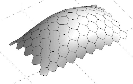
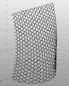
Although Revit includes a variety of patterns you can use for conceptual curtain walls, at present there is no way to create your own pattern-based curtain panel template. The current patterns shipped with Revit are hardwired so there is no way to modify them either; however, with a bit of creative thinking you can utilize the provided templates to construct panels that will conform to a custom pattern concept. When you consider building a custom panel, it is important to take into account how it will repeat vertically and horizontally. You will need to break it down into to its smallest module. If you think about a repeating architectural pattern such as a masonry wall, its individual component can be broken down into the brick that forms that pattern, which is in essence a rectangle. An example of a hexagon-shaped panel, constructed within a rectangular pattern, is shown in Figure 13.72.
FIGURE 13.72 A hexagonal panel is constructed within a standard rectangular pattern.

Once you have decided on the design for your panel, look at how the panel could be modularized. To do this, consider laying out the pattern utilizing graph paper. This will certainly help you better understand the layout before attempting to construct the panel using an appropriate template. In Figure 13.73, you will see the hexagonal panel applied across a divided surface.
FIGURE 13.73 The hexagonal panel applied across a divided surface
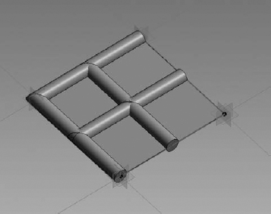
Limiting the Size of Pattern-Based Families
When designing complex curtain wall systems, the goal is to limit the variety of panels. The more variety you have, the higher the cost because you have to create a greater number of unique panels. When you divide a surface in Revit, the panel sizes can vary quite dramatically. While Revit does not actually offer the ability to limit panel sizes, you can start to reduce the size and variety of panels by nesting curtain panels inside other panels. In the following exercise, you will learn how to nest panels to limit size variation.
- Start by creating a simple pattern-based curtain panel family (use either Curtain Panel Pattern Based.rft or M_Curtain Panel Pattern Based.rft). Make sure the grid is set to the Rectangular type.
- Select the four reference lines and use the Create Form tool to generate a planar surface.
- Similar to the previous exercise, place a hosted point on one of the edges of the surface and then draw a circle with a 6″[150mm] radius on the point's work plane. Use Create Form to generate a swept profile on two edges to represent a mullion, as shown in Figure 13.74. Save this panel as Limit-Panel-1.rfa.
- Start another new pattern-based curtain panel family, again using the Rectangular grid pattern. Select the four reference planes and use Create Form to generate a planar surface rather than an extrusion.
FIGURE 13.74 A panel with a swept profile is created to be nested into another panel family.
- Select the planar surface and click the Divide Surface tool from the ribbon. You will divide this surface and set the UV grid by number, setting U Grid = 2 and V Grid = 2, as shown in Figure 13.75.
FIGURE 13.75 Create another pattern-based family and divide the surface into a 2 × 2 grid.

- Load the Limit-Panel-1 family into the divided surface panel.
- Select the divided surface and apply your panel to the divided surface by choosing Limit-Panel-1 from the Type Selector. This will nest the panel into the subdivisions of the divided surface (Figure 13.76). Save this panel as Limit-Panel-2.rfa.
FIGURE 13.76 The simple panel is nested into the divided surface of the host panel.
You can now apply this nested panel into any divided surface. Download and open the file c13-Limit-Panel-Project.rfa from this book's companion web page.
- In the c13-Limit-Panel-Project.rfa file, select the pattern and divided surface. From the Type Selector, select the name Limit-Panel-2. Note that your new panel family will be listed under the pattern within which it was designed. It will take a few seconds for Revit to replace the pattern with the real geometry of the panel. But observe that by nesting the panel inside other panels you have been able to limit the size and variety of the panels (Figure 13.77).
FIGURE 13.77 The host panel containing the nested panel is populated on a divided surface.


Using the Adaptive Component Family
So far the examples covered look at using the UV grid to nest in curtain wall pattern–based families; however, there will be situations where you may want to manually place a panel, specifically at border conditions where you may need to construct custom panels. To do this, use the Adaptive Component functionality that is available to you in the pattern-based curtain panel. This functionality is designed to handle cases where components need to flexibly adapt to many unique related conditions. This new functionality also addresses the problems of creating and placing pattern component panels (triangular, pentagonal, hexagonal, and so on) on nonrectangular and irregularly spaced grids. In the following exercise, you will create an adaptive panel and manually place it along the border of a divided surface.
- Create a simple pattern-based curtain panel family (Curtain Panel Pattern Based.rft or M_Curtain Panel Pattern Based.rft) and use the rectangular grid pattern. Select each of the four adaptive points and notice that each point has a number from 1 to 4.
- Select one of the points; then from the Properties palette change the Show Placement Number parameter to Always.
- Select all the reference planes in the family and choose Create Form; select the Planar Surface option. Save this panel as My Adaptive Panel.rfa.
- Download and open the file c13-StitchSurface-Project.rfa from this book's companion web page.
- Load the panel you previously created into c13-StitchSurface-Project.rfa.
Notice that in c13-StitchSurface-Project.rfa the UV grid has been enabled as well as the nodes at the intersections of the UV grid (Figure 13.78). You will use these nodes to snap your panel.
FIGURE 13.78 Sample surface with nodes displayed

- Locate the Families category in your Project Browser and expand the Curtain Panel tree. You will find the My Adaptive Panel type in this list. Drag it into the 3D view window.
- With the panel attached at your mouse pointer, place the pointer onto one of the nodes on the subdivided surface to place the first point. Place the remaining points onto the corresponding nodes, as shown in Figure 13.79. Observe how the panel will adapt based on its placement in the surface division.
FIGURE 13.79 Placing an adaptive panel into a divided surface

Scheduling Pattern-Based Panels
Now that you have completed the design of your pattern-based curtain wall families, you may want to use Revit's scheduling capabilities to assess the quantity and area of panels in your conceptual curtain wall system. This can be useful for calculating approximate costs at the early stages of design. You can schedule panels that have been applied to an in-place mass directly in the project environment; however, it is not possible to schedule panels in the conceptual design environment. You will first have to load your concept mass into a project, where you will then be able to schedule the panels. In this example, you will open a sample file, load it into a project, and then create a schedule, which will list all the panels that make up your conceptual curtain wall.
- Download and open the file c13-Square-Panel-Schedule.rfa from this book's companion web page.
- Start a new project using either default.rte or MetricDefault.rte; then load the file c13-Square-Panel-Schedule.rfa into your new project.
- From the Massing & Site tab in the ribbon, click the Place Mass button and select c13-Square-Panel-Schedule from the Type Selector. Make sure that the Place On Workplane icon is selected in the Placement panel and place the massing component in the Level 1 floor plan.
- Open the default 3D view to view your model (Figure 13.80).
FIGURE 13.80 A conceptual curtain wall is loaded into a project and placed using Place Mass.
- From the View tab in the ribbon, click Schedules and then click Schedules/Quantities. This will open the New Schedule dialog box. Select Curtain Panels from the Category list and click OK.
- You will now define the fields that will be included within your panel schedule. Choose Family in the left column and click the Add button to add this field to your schedule. Next add Area and then Count.
- Click the Sorting/Grouping tab and check the options for Grand Totals and Itemize Every Instance.
- Click the Formatting tab and select the Area field. Make sure the Calculate Totals option is selected. Do the same for Count.
- Click OK and your schedule will be created. If you scroll down to the bottom of the schedule, the total area and the number of custom panels in your conceptual curtain wall will be listed.
THANKS TO DAVID LIGHT
A portion of this chapter was written with the help of David Light. David Light is the Revit Specialist for HOK London, focusing on Revit and BIM as well as helping to drive forward the firm's global buildingSMART principles. David was first introduced to Revit at version 4.5 just after the Autodesk acquisition and has had an unhealthy passion for the technology ever since. Before joining HOK, David worked for the UK's Autodesk Premier Solutions Center providing coaching, training, and consultancy in Revit Architecture and Revit Structure. David has developed a reputation as one of the leading UK experts in Revit and is a popular speaker and blogger on all things Revit and BIM.