Creating Simple Curtain Walls
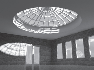
Curtain walls and curtain systems in Revit are unique wall types that allow you to embed divisions, mullions, and panels directly into the wall. They have a distinct set of properties, yet still share many characteristics of basic walls. A curtain system has the same inherent properties of a curtain wall, but it is used when you need to apply a curtain wall to a face. Curtain systems are usually nonrectangular in shape, such as the glazed dome shown in Figure 13.34.
FIGURE 13.34 Glazed dome created with a curtain system
A curtain wall is defined by the following elements and subcomponents:
The Curtain Wall A curtain wall is drawn like a basic wall and is available in the Type Selector when the Wall tool is activated. It has top and bottom constraints, can be attached to roofs or reference planes, can have its elevation profile edited, and is scheduled as a wall type. When a curtain wall is selected in a model, the overall curtain wall definition is displayed as a dashed line with extensions at both ends of the segment:
The dashed line of the overall curtain wall definition represents the location line of the wall. This is important if you are placing a curtain system on a face because the placement will be based on the location line. The location line of a curtain wall also determines the measurement of room area. Even if the Room Area Computation option is set At Wall Finish, a room's area will be measured to a curtain wall's location line. For more information, refer to a post on the Do U Revit blog (http://do-u-revit.blogspot.com/2010/04/room-area-and-curtain-walls.html).
So, how do you adjust the location line of a curtain wall? This is accomplished by modifying the offsets in the mullions and panels you assign to a curtain wall or system. We'll cover this process in the section “Customizing Curtain Wall Types,” later in this chapter.
Curtain Grids These are used to lay out a grid, defining the physical divisions of the curtain wall. You can lay out grids freely as a combination of horizontal and vertical segments, or they can be predefined in a curtain wall's Type Properties in regular spacing intervals. Figure 13.35 shows a freely designed layout of curtain grids and expressive curtain panels in between.
FIGURE 13.35 Curtain wall with regular orthogonal grids and expressive curtain panels

Mullions These represent the structural profiles on a glass façade and in Revit they follow the curtain grid geometry. Mullions can be vertical or horizontal and can be customized to any shape based on a mullion profile family. Offsets specified in a mullion's Type Properties affect how the mullion is placed relative to the curtain wall's location line.
Curtain Panels These fill in the space between the curtain grids. Offsets in a curtain panel's Type Properties determine how the panel is placed relative to the curtain wall's location line. Curtain panels are always one of the following:
Empty Panels No panel is placed between the grids.
Glazed Panels These can be made out of different types of glass that can have any color or transparency.
Solid Panels Panels can be created with custom geometry in the Family Editor and can include anything from doors to spandrels to shadow boxes to solar fins.
Wall Types as Infill When you have a panel selected, you can also choose a basic wall type from the Type Selector to fill the space between the curtain grids. All wall types in the project will be available for your selection. An example of this application would be interior office partitions in which the lower portion is a standard wall and glass panels fill the upper portion.
Designing a Curtain Wall
Let's go through a quick exercise to become familiar with the creation of a simple curtain wall. To create a curtain wall, you can either model a standard wall, then change its type to Curtain Wall, or select a curtain wall type from the Type Selector when the Wall tool is active.
- From the Home tab in the ribbon, select the Wall tool. From the Type Selector (in the Properties palette) select Curtain Wall 1.
- In the Level 1 floor plan, draw a single curtain wall. Go to a 3D view to see the result.
The basic curtain wall definition has no predefined grids or mullions. The wall segment you see is just one big system panel that you will need to divide. Note that if you create a curved segment for a curtain wall, the panels are always straight segments. Thus, if you try to make a curved segment with Curtain Wall 1, there will only be one straight panel segment between the endpoints of the curve until you start to divide it up with curtain grids.
- Divide the wall into panels using the Curtain Grid tool from the Home tab. Position your mouse pointer over the edges of the wall to get a preview of where the grid will be placed (select a vertical edge to place a horizontal grid or select a horizontal edge to place a vertical grid).
Revit offers some snapping options when you are placing curtain grids that will help you divide the panels and subsequent divisions at midpoints and thirds. Watch the status bar for snapping prompts because there are no graphic indicators of the snapped positions other than the mouse pointer pausing. Place grids on the wall segment so that you get something like the wall shown in Figure 13.36.
- From the Home tab, select the Mullion tool. Notice that you can select from a variety of mullion types in the Type Selector; however, the default choice is adequate for this exercise. At the right end of the ribbon, you will see the Placement panel with three options for placing mullions: Grid Line, Grid Line Segment, and All Grid Lines. You can place mullions on the curtain wall using any of these methods. Give each a try to see how they work.
FIGURE 13.36 Curtain wall with a few manually applied grids

MODIFYING PANELS AND MULLIONS
![]() Next you'll replace panels in the wall you just created. As we explained earlier, panels are subcomponents of the overall curtain wall, so you may need to press the Tab key to select a panel and view its properties. Revit has special selection tools for curtain walls that are available in the right-click context menu when you highlight a mullion or a panel. In the following exercise, you will replace the narrow band of glazing panels with solid panels.
Next you'll replace panels in the wall you just created. As we explained earlier, panels are subcomponents of the overall curtain wall, so you may need to press the Tab key to select a panel and view its properties. Revit has special selection tools for curtain walls that are available in the right-click context menu when you highlight a mullion or a panel. In the following exercise, you will replace the narrow band of glazing panels with solid panels.
- In a 3D view, select one of the glazing panels in the narrow horizontal band (press the Tab key to select it if necessary).
- From the right-click context menu, choose Select Panels
 Along Horizontal Grid, as shown in Figure 13.37.
 - With all the glazing panels selected along the horizontal grid, go to the Type Selector and find the type named Solid under the family system panel note that the Glazing panel type is in the same family as the Solid panel).
FIGURE 13.37 Select multiple curtain panels along a grid with commands in the right-click menu.

CUSTOMIZING CURTAIN GRID SEGMENTS
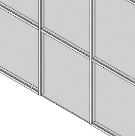
Finally, you will practice the techniques to add or remove segments of curtain grids to refine our curtain wall design. One important fact to remember when working with curtain grids is that they are always implied across the extents of the curtain wall. When we say they are implied, we mean they are not necessarily expressed on all panel segments. To further elaborate, you will add a curtain grid to the midpoint of the right, center panel and delete the division between the two panels to the left of the added grid, as shown in Figure 13.38.
- Begin by activating the Curtain Grid tool from the Home tab. In the Placement panel at the right end of the ribbon, click the One Segment button. Hover your mouse pointer over the bottom edge of the right-center panel, snapping to the midpoint of the panel (Figure 13.39).
FIGURE 13.38 Individual grid lines are added or deleted to further customize the design.

FIGURE 13.39 A single segment is added to the center panel of the curtain wall.
- The second step is tricky. You do not continue creating another division in the short panel above the center panel. Instead, press the Esc key or click the Modify tool to exit the Curtain Grid command. Select the vertical grid line you created in step 1 (you may need to press the Tab key until you see the dashed line indicating the curtain grid). Notice that the grid extends the entire height of the wall (Figure 13.40).
FIGURE 13.40 Select the curtain grid in order to add or remove individual segments along the grid.
- With the curtain grid selected, click the Add/Remove Segments button in the Modify | Curtain Grids panel of the ribbon. Pick the segment of the curtain grid that passes through the short panel. Press the Esc key and you should see that the short panel is also split in half.
- Activate the Mullion tool and place mullions on the division between the two center panels, as shown in Figure 13.41.
FIGURE 13.41 Mullions are applied to the segment added in the center panels.

- Press the Esc key or click Modify. Select and delete the horizontal mullion between the two left panels (this step is optional).
- Similar to the process of adding grid segments, select the horizontal curtain grid below the narrow band and click the Add/Remove Segments button in the ribbon. Click the segment in the left-center panel. If you did not delete the mullion in step 5, a warning will appear prompting you to delete the mullion segment. The result should look like the wall shown in Figure 13.42.
FIGURE 13.42 A segment was removed from the left panel to complete the customized design.


PLACING DOORS IN CURTAIN WALLS
In the final exercise of this section, you will swap one of the curtain panels for a door panel. Door families for curtain walls can be found in the Doors folder of Revit's default library, but they behave differently than regular doors. The height and width of the curtain wall door is driven by the curtain grids—not the Type Properties of the door.
- From the Insert tab on the ribbon, locate the Load From Library panel and click the Load Family button. Navigate to the Doors folder of Revit's default library and load the Curtain Wall Dbl Glass.rfa family.
- Zoom into the bottom-middle panel in your curtain wall. Delete the mullion under this segment as shown in Figure 13.43 (you don't want to have a tripping hazard at your door!). Remember, you may have to press the Tab key to select the mullion.
FIGURE 13.43 Delete the mullion below the panel where the door will be placed.
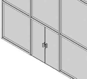
- Select the bottom-middle panel and go to the Type Selector. Find the Curtain Wall Dbl Glass.rfa family and select it from the list so the results look like the wall in Figure 13.44. The door swing can be adjusted in plan as any other door in Revit.
FIGURE 13.44 System glazing panel has been swapped for a double door panel family.
PLACING CORNER MULLIONS
Revit includes special mullions to be used at the corners of two curtain walls. These mullion types are unique in that only one is needed to connect two wall segments. In the default project template you will find four corner mullion types, as shown in Figure 13.45: (a) V Corner Mullion, (b) Quad Corner Mullion, (c) L Corner Mullion, and (d) Trapezoid Corner Mullion.
FIGURE 13.45 Available curtain wall corner mullions

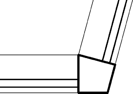
Corner mullions cannot be customized beyond the shapes included in the Revit project template; however, you can modify the material assigned to the mullions as well as the offset and depth dimensions in the Type Properties. When you use corner mullions between two segments of curtain wall, they will automatically adjust to the angle between the segments, as shown in Figure 13.46.
FIGURE 13.46 Corner mullions adapt to angles between curtain wall segments.
Before you place a corner mullion, make sure that the endpoints of the two curtain wall segments are cleanly connected. You can drag the endpoint controls of the walls or use the Trim/Extend To Corner tool. To place a corner mullion, simply use the Mullion tool and select one of the corner edges of either one of the wall segments. If you have already placed a regular mullion at the end of a curtain wall segment, select the mullions along the vertical edge and then use the Type Selector to choose a corner mullion type. Remember you can use the right-click menu (select Mullions ![]() On Gridline) to make the selection easy.
On Gridline) to make the selection easy.
Customizing Curtain Wall Types
In the previous exercises you learned the fundamental techniques of building a simple but custom curtain wall design. To reap some additional productivity from the curtain wall tool, you can predefine almost all the properties necessary to generate a complete curtain wall assembly simply by placing the wall in your project. In the following sections we will examine one of the curtain wall types included with Revit's default project template.
Begin a new project with the Default.rte or MetricDefault.rte template and create a wall segment 30′ [9000mm] long using the type Curtain Wall: Storefront. Switch to a 3D view and you will see the wall already has vertical and horizontal divisions along with mullions placed on the divisions. In the example shown in Figure 13.47, we have placed an additional curtain grid and swapped one of the panels for a door type.
FIGURE 13.47 Sample curtain wall storefront type

Select the sample of Storefront wall you had previously created and click the Edit Type button in the Properties palette. The settings that drive the generation of this type of wall are relatively easy to understand. Let's review some important options related to these properties:
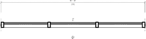
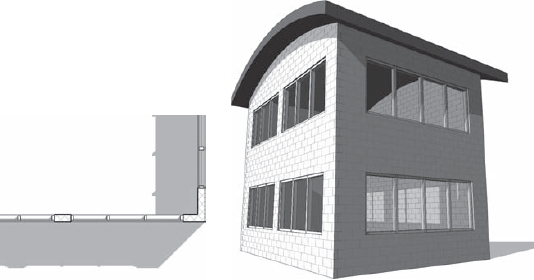
Automatically Embed When this option is enabled, any instance of this curtain wall type will embed itself inside other wall segments. This is useful for modeling extended areas of ribbon or strip glazing (Figure 13.48) instead of using a window family.
FIGURE 13.48 The Automatically Embed option allows curtain walls to be placed inside basic walls.
Join Condition This option defines the behavior of the mullion joins. It can be one of the following:
- Not Defined (join conditions can be overridden as necessary)
- Vertical Grid Continuous
- Horizontal Grid Continuous
- Border And Vertical Grid Continuous
- Border And Horizontal Grid Continuous
Grid Pattern: Layout There are four options to define how the vertical and horizontal grids will be arranged in your curtain wall.
Fixed Distance The most common setting, which allows you to specify spacing between gridlines. Leftover panel segments must be accounted for in the overall length of the wall.
Fixed Number Divides the wall segment into equally spaced panels. When you select this option, the Spacing parameter becomes disabled. In its place, a new integer parameter named Number will appear in the instance properties.
Maximum Spacing Indicates the maximum spacing distance. Curtain panels will be equally divided over the length of the wall segment, not to exceed the Spacing value.
Minimum Spacing Indicates the minimum spacing distance. Curtain panels will be equally divided over the length of the wall segment, no smaller than the Spacing value.
Mullions This option allows you to specify the mullions that will be automatically applied to the curtain wall. Corner mullions can be applied to either Border 1 or Border 2 for the vertical mullions, but use them carefully—their resolution at corners will depend on how you construct your wall segments.
MODIFYING PINNED PANELS AND MULLIONS
You may have already noticed when a panel or mullion is selected from a predefined curtain wall type that they appear with a pushpin icon. This indicates that these elements are part of a system and cannot be changed without additional action.
To change or delete a predefined panel or mullion in a curtain wall instance, select the element and click the pushpin icon. The icon will change to a pushpin with a red X next to it. At this point, you can change the element using the Type Selector or delete it (only mullions can be deleted). Be careful when you attempt to unpin elements from a curtain wall as you cannot re-pin back to the predefined system. Within the active session of Revit, you may be able to return to an unpinned curtain wall element and still find the unpinned icon. This allows you to fix any accidental unpinning, but once your project is closed and reopened, you can no longer reassociate the unpinned elements.
CREATING CUSTOM CURTAIN PANELS
A curtain panel does not have to be confined to a simple extrusion of glass or solid material. You can create any kind of panel family to satisfy your design requirements. When creating a new panel, be sure to select the Curtain Wall Panel.rft or Metric Curtain Wall Panel.rft family template file. The width and height of the panel are not explicitly specified in the family; instead, the outermost reference planes will adapt to the divisions in the curtain wall into which the panel is embedded. If required, you can adjust the panel geometry to offset within or beyond the reference plane boundaries in the family. This is useful for creating butt-glazed curtain wall assemblies.
COMPLEX CURTAIN WALL APPLICATIONS
Although covering several specific examples in detail is outside the scope of this chapter, we will offer some real-world examples of creating your own custom curtain panels. Refer to Chapter 15 for guidance on creating your own families. These examples are included in a sample file named c13-Curtain-Wall-Custom.rvt on this book's companion web page (www.sybex.com/go/masteringrevit2012).
Spider Fittings and Sunshades Generic models can be nested in a curtain panel family. In the example shown here, two instances of the spider component are placed on one edge of the panel. Visibility parameters are assigned to the two spider fittings that enable either the top or bottom spider to be displayed as needed. The spider fittings were downloaded from RevitCity.com and the sunshade is a Kawneer model 1600 SunShade – Planar downloaded from Autodesk Seek (http://seek.autodesk.com).

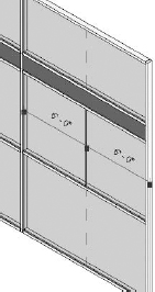
Spandrel and Shadowbox Often in glazing applications, the spacing of horizontal members will consist of a pattern including a narrow band or spandrel to mask the floor and ceiling sandwich. Revit does not currently have the ability to define two spacing values, but you can create the spandrel or shadowbox in a single panel family. In the example shown here, the spandrel height is a type property of the custom panel family. Standard mullions are applied to the wall.

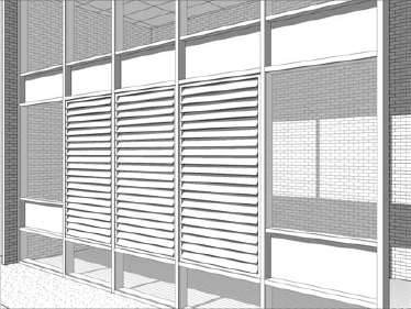
Louvers Our last example shows how metal louvers can be embedded in a curtain panel family. The image shown here is a panel developed with a nested generic model. The louver fins are arranged in a parametric array within the generic model, and then the generic model is placed in the panel. The edges of the louver array are constrained to the reference planes in the panel. This parametric louver curtain panel was downloaded from RevitCity.com.