
Energy Modeling
Understanding a building's energy needs is paramount to helping the project become more sustainable. According to the U.S. Energy Information Administration (www.eia.doe.gov), buildings in the United States account for 30 percent of the world's energy and 60 percent of the world's electricity, making the United States the primary consumer of energy in the world and the built form the largest consumer (Figure 10.26). This reality will hopefully inspire you to build responsibly and to think about your design choices before you implement them.
FIGURE 10.26 Energy use in the United States

The energy needs of a building depend on a number of issues that are not simply related to leaving the lights on in a room that you are no longer using or turning down the heat or increasing the air conditioning. Many of the components and systems within a building affect its energy use. For instance, if you increase the windows on the south façade, you allow in more natural light and lower your need for electric lighting. However, without proper sunshading, you are also letting in additional solar heat gain, with those larger windows increasing your need for more air conditioning and potentially negating the energy savings from lighting.
In exploring the use of energy in a building, you must consider all related energy issues, which is good reason to use energy simulation tools. These computer-based models use climate data coupled with building loads, such as the following:
- The heating, ventilation, and air conditioning system (HVAC)
- Solar heat gain
- The number of occupants and their activity levels
- Sunshading devices
- Daylight dimming
- Lighting levels
The energy model combines these factors to predict the building's energy demands to help size the building's HVAC system and parameters of other components properly so you are not using a system larger than what you need and so you can understand the impact of your design on the environment. By keeping the energy model updated with the current design, you can begin to grasp how building massing, building envelope, window locations, building orientation, and other parameters affect energy demands.
There are two ways you can use Revit for energy analysis—by analyzing mass forms directly in Revit or by exporting a more detailed model to other applications using the gbXML format. For either choice, you must first have accurate location and true north settings. Once you have those established, you can approach either analysis with confidence. Let's first take a look at the process for generating a conceptual energy analysis.
Using Revit for Conceptual Energy Analysis
One of the primary benefits of using BIM tools is the ability to make informed design decisions earlier in the process of developing your project. The massing tools in Revit were developed precisely for this purpose. Before you even think of adding walls, doors, floors, and windows to your design, you can generate a conceptual model and assess the environmental impact of the overall proportions, orientation, and general construction assumptions.
A conceptual energy analysis (CEA) tool was added to Revit as a Subscription Advantage Pack in late 2010. This tool is now available in Revit Architecture 2012. It creates a link to the online analysis service known as Green Building Studio (www.autodesk.com/greenbuildingstudio) using the massing geometry in your project. The results will indicate such information as the life cycle and annual energy costs. In our opinion, it is wise to only use the CEA tool to determine which results are better or worse than others. If you convince your clients that these are the actual costs and they turn out to be too low when the building is constructed, will you be held responsible for the discrepancy?
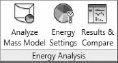
In the following exercise, you will use a sample project with two different design options for massing. There are three basic tools for configuration, analysis, and comparison of results in the Analyze tab of the ribbon (Figure 10.27).
FIGURE 10.27 The Analyze tab in the ribbon
NOTE You will need an Autodesk Subscription account to access the Green Building Studio service and utilize the CEA tools.
- Begin by opening the file c10-Masses.rvt from this book's web page.
- On the Analyze tab, click Energy Settings. The first step is to establish the correct location of your project. Click the selection button at the end of the Location property to open the Location Weather And Site dialog box (Figure 10.28). Type Brisbane, Australia in the Project Address field and click Search. Click on one of the closest weather stations in the list or directly on the map.
FIGURE 10.28 In Energy Settings, first specify the location and weather station.

- For this exercise, we will assume that the building type is an office. You may choose to change this assumption for your own project at the top of the Energy Settings dialog box.
- Select the Create Energy Model check box and click the Conceptual Constructions edit button. The dialog box that appears (Figure 10.29) allows you to specify various assumptions for the construction of your building design.
FIGURE 10.29 Specify assumptions for the construction type based on your mass model.

- Leave the initial conceptual construction assumptions and click OK to close the dialog box.
Remember that this type of analysis is based on assumptions only and uses the overall size, location, and orientation of your proposed design. After you start analyzing the results, you can either examine different massing configurations with the same construction and systems assumptions or vice versa.
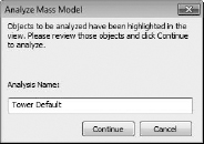
- Click the Analyze Mass Model button to start the analysis. Name this analysis run Tower Default (Figure 10.30). Revit will start to communicate with the Green Building Studio service.
FIGURE 10.30 Name each analysis run for easy comparison.
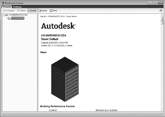
- Click the Results and Compare button to view the progress of the upload. If you don't have the Results and Compare dialog box open, an alert will appear in the lower right of the Revit window informing you that the analysis is complete. Once it is complete, you will see the run listed under the name of the model you are analyzing, as shown in Figure 10.31.
FIGURE 10.31 The Results And Compare window
The next step will be to change some of the assumptions and run the analysis again to determine the impact of the changes on the energy usage. We are only showing you a small number of options, but again realize that you can explore many alternatives of building size, orientation, glazing percentages, and more.
- Go back to the main Revit application and click the Energy Settings button again. Select the Glazing Is Shaded property and set the Shade Depth value to 2¢-02 [500 mm].
- Click the Conceptual Constructions edit button and change the Mass Glazing setting to Double Pane Clear - High Performance, LowE, High Tvis, Low SHGC. Click OK to close both dialog boxes.
- Click the Analyze Mass Model button again and name this run Tower with Shaded LowE Glazing.
- After the run has completed, return to the Results and Compare window and select both the Tower Default and Tower with Shaded LowE Glazing runs by pressing the Ctrl key. Click the Compare command.
You will see the results of the two analysis runs side by side. Notice that the second run has a lower monthly electricity consumption and lower fuel consumption. Be careful when reading the graphs because the values in each graph may be different. Take a look at the graphs for Monthly Cooling Load. Notice that the values for Window Solar are lower for the second run; however, the values for Light Fixtures are slightly higher. This is due to the addition of the shading, which requires more electric lighting power.
In this exercise, we showed you how to change overall assumptions for the building; however, you can also select parts of the energy model or mass in a 3D view and override the energy settings for specific parts of your building. For example, you might want to add shading to the south façade only or perhaps customize the glazing percentage on each building face.
As you can see, generating a sustainable design for your projects is a process of testing a variety of options and comparing the results. We have shown you a simple example to give you familiarity with the basic process. It is up to you to explore these options further in the context of your own designs.
Detailed Energy Modeling
Later in the design process, you may want to use your building model to perform more detailed energy modeling. For this process to be successful, you first need a solid, well-built model. This does not mean you need all the materials and details figured out, but you do have to establish some basic conditions. To ensure your model is correctly constructed to work with an energy modeling application, there are a few things that you need to do within the model to get the proper results. Some of this might sound like common sense, but it is important to ensure that you have the following elements properly modeled or you can have incorrect results:
- The model must have roofs and floors.
- Walls inside and outside need to touch the roofs and floors.
- All areas within the analysis should be bound by building geometry (no unbound building geometry allowed).
To perform an energy analysis, you need to take portions of the Revit file and export them using gbXML to an energy analysis application. The following are the energy modeling applications commonly used within the design industry. Each varies in price, ease of use, and interoperability with a gbXML model. Choosing the correct application for your office or workflow will depend on a balance of those variables.
IES <VE> IES <VE> (www.iesve.com) is a robust energy analysis tool that offers a high degree of accuracy and interoperability with a BIM model. The application can run the whole gamut of building environmental analysis from energy to daylighting to Computational Fluid Dynamics (CFDs) used to study airflow for mechanical systems. Cons to this application are its current complexity for the user and the relatively expensive cost of the tool suite.
Autodesk Ecotect Analysis This application (www.autodesk.com/ecotect-analysis) has a great graphical interface and is easy to use and operate. The creators of this application also have a number of other tools, including a daylighting and weather tool. While the program is easy to use, it can be challenging to import model geometry depending on what application you are using for your BIM model. For example, SketchUp and Vectorworks can import directly, whereas applications like Revit can be more of a challenge.
eQuest The name stands for the Quick Energy Simulation Tool (www.doe2.com/equest). This application is a free tool created by the Lawrence Berkeley National Laboratory (LBNL). It's robust and contains a series of wizards to help you define your energy parameters for a building. Like Ecotect, it can be a challenge to import BIM model data smoothly depending on the complexity of the design, although it will directly import SketchUp models by using a free plug-in.
Exporting to gbXML
Before you can export the model to gbXML and run your energy analysis, you need to create several settings within Revit so you can export the proper information. It isn't important in which order these options are set, but it is important to check that they are set before exporting to gbXML. If the information within the model is not properly created, the results of the energy analysis will be incorrect.
PROJECT LOCATION
As we mentioned earlier in this chapter, the physical location of the project on the globe is an important factor in energy use analysis. In Revit, you can give your building a location in a couple of ways. One is to choose the Manage tab and click the Location button. Another way to get to this same dialog box is through the Graphic Display Options you used for solar shading earlier in this chapter.
BUILDING ENVELOPE
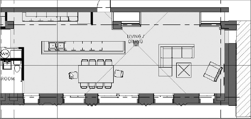
Although this might seem obvious in concept, a building without walls cannot have an accurate energy analysis run on it. Although the specific wall or roof composition won't be taken into account, each room needs to be bound by a wall, floor, or roof. These elements are critical in creating the gbXML file and defining the spaces or rooms within the building. These spaces can in turn be defined as different activity zones in the energy analysis application. Before you export, verify that you have a building envelope free of unwanted openings. This means all your walls meet floors and roofs and there are no “holes” in the building (Figure 10.32).
FIGURE 10.32 Make sure your building envelope is fully enclosed.

ROOMS AND VOLUMES
When Revit exports to a gbXML file, it is actually exporting the room volumes as they are constrained by the building geometry. This is what will define the zones within the energy analysis application. There are several steps you will need to verify to make sure your rooms and room volumes are properly in place:
Ensure all spaces have a room element. Each area within the Revit model that will be affected by the mechanical system will need to have a room element added to it. To add rooms, select the Room tool from the Home tab. Placed rooms within the model will look like Figure 10.33.
Set room heights. Once all the rooms are placed, each room's properties should be redefined to reflect its height. The height of the room should extend to the bottom of the room above (in a multistory building), or if it is the top/only floor of a building, the room must fully extend through the roof plane. When you extend the room through the roof plane, Revit will use the Roof geometry to limit the height of the room element and conform it to the bottom of the roof. Rooms should never overlap either in plan (horizontally) or vertically (between floors) as this will give you inaccurate results.
An easy way to set the room heights is to open each level and select everything on the level. Using the Filter tool (Figure 10.34), you can unselect all the elements and choose to only keep the rooms selected. In this way, you can edit all the rooms on a given floor at one time.
FIGURE 10.34 Use the Filter tool to select only the rooms.

Once the rooms are selected, go to the Properties palette and modify the room heights. By default, rooms are inserted at 8¢-02 high. You have the option to set a room height directly, or you can modify the room height settings to go to the bottom of the floor above. This second option is what you have set for our rooms and is shown in Figure 10.35. Note that you'll need to set Upper Limit to the floor above and delete the value (10¢-02 [3000 mm] by default) in the offset. Repeat this same workflow for every floor of the building.
FIGURE 10.35 Modifying the room height

Turn on room volumes. Now that all the heights are defined, you have to tell Revit to calculate the volumes of the spaces. By default, Revit does not perform this calculation. Depending on the size of your file, leaving this setting on can hinder performance. Make sure that after you export to gbXML you return to this dialog box and change the setting back to Areas Only.
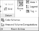
To turn on room volumes, select the flyout menu from the Room panel on the Home tab (Figure 10.36) and click Area And Volume Computations.
FIGURE 10.36 Opening Area And Volume Computations
Doing so opens the Area And Volume Computations dialog box. There are a couple of simple settings here that will allow you to activate the volume calculations within Revit (Figure 10.37). You'll want to select the radio button Areas And Volumes so that Revit will calculate in the vertical dimension as well as the horizontal for your room elements.
FIGURE 10.37 Enabling volume calculations for rooms

The second setting tells Revit where to calculate the rooms from. If you choose Wall Finish, Revit will not calculate any of the space a wall actually takes up with the model. Arguably, this is also conditioned space. Technically, what you would want is to calculate from the wall centers on interior partitions and the interior face of wall on exterior walls. However, Revit does not give you that option, so choose to calculate from At Wall Center. Once you've modified those settings, click OK.
EXPORTING TO GBXML
Now that you have all the room settings in place, you're ready to export to gbXML. To start this process, click the Application menu and select Export ![]() gbXML. A dialog box that looks like Figure 10.38 will open.
gbXML. A dialog box that looks like Figure 10.38 will open.
FIGURE 10.38 Exporting gbXML settings

There are a few things to take note of in this dialog box. First, you'll see a 3D image of the building showing all the room volumes and bounded by the exterior building geometry. You can see in our building visualization that the boundary for the building is not completely full of room elements and that some of the room elements do not visually extend to the floor above. This would be your first clue that all your rooms do not have room elements placed or set properly, and you'll want to dismiss this dialog box to change those settings.
Second, you'll notice the ViewCube at the upper right of the 3D view window. This window will respond to all the same commands as a default 3D view will directly in Revit, allowing you to turn, pan, and zoom the visualization.
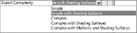
There are also two tabs on the right of this dialog box. The General tab will contain general information about your building and you'll want to verify it is filled out properly. Some of this information is Building Type, Postal Code (Zip Code), Ground Plane, and Project Phase. These settings will help determine the building use type (for conceptual-level energy modeling) and the location of your building in the world. There are two other settings: Sliver Space Tolerance and Export Complexity. Sliver Space Tolerance will help take into account that you might not have fully buttoned up your Revit building geometry. This will allow you a gap of up to a foot and Revit will assume that those gaps (122 or less) are not meant to be there. The Export Complexity setting allows you to modify the complexity of the gbXML export. There are several choices (Figure 10.39) based on the complexity of your model and the export.
FIGURE 10.39 Exporting complexity settings
The Details tab will give you a room-by-room breakdown of all the room elements that will be exported in the gbXML model. Figure 10.40 shows the expanded Details tab. This is an important place to check as you'll also notice that this dialog box will report errors or warnings with those room elements.
FIGURE 10.40 The Details tab allows you to examine any errors or warnings.

![]() If you expand any of the levels and select a room, clicking the warning triangle will give you a list of the errors and warnings associated with that room (Figure 10.41). You'll want to make sure your gbXML export is free of any errors or warnings before completing the export.
If you expand any of the levels and select a room, clicking the warning triangle will give you a list of the errors and warnings associated with that room (Figure 10.41). You'll want to make sure your gbXML export is free of any errors or warnings before completing the export.
FIGURE 10.41 Clicking the warning button will display the problems related to the selected room.

Once you're ready to finish the export, click Next. This will give you the standard Save As dialog box, allowing you to locate and name your gbXML file. Depending on the size and complexity of your building, a gbXML export can take several minutes and the resulting file size can be tens of megabytes.
You're now ready to import the gbXML file into your energy analysis application to begin computing your energy loads.