Creating Stacked Walls
Walls in a building—especially exterior walls—are often composed of several wall types made out of different material combinations and with different widths that stack one on top of another over the height of the façade. Because these walls usually sit on top of a foundation wall, you would likely want to establish an intelligent relationship among these different wall assemblies so the entire façade acts as one wall (for example, when the foundation wall moves and you expect walls on top of the foundation to also move). This is where stacked walls can help.
![]() Stacked walls allow you to create a single wall entity composed of different wall types stacked on top of each other. Before you can create a stacked wall, some basic wall types need to be preloaded in your project. To help you understand how stacked walls work and how to modify one, follow these steps:
Stacked walls allow you to create a single wall entity composed of different wall types stacked on top of each other. Before you can create a stacked wall, some basic wall types need to be preloaded in your project. To help you understand how stacked walls work and how to modify one, follow these steps:
- Open a new session of Revit and make sure at least three levels are defined. If you don't have three levels, switch to an elevation view, add a few levels, and then go back to the Level 1 floor plan view.
- From the Home tab on the ribbon, pick the Wall tool and select Stacked Wall: Exterior – Brick Over CMU w Metal Stud (you can find stacked wall types at the bottom of the list in the Type Selector). Draw a segment of wall in the Level 1 floor plan.
- Select the wall segment. In the Properties palette, click the Edit Type button and then duplicate the wall type to create a new stacked wall called Mastering Stacked Wall.
- Click the Edit button in the Structure field to open the Edit Assembly dialog box. Open the preview pane and set the view to Section. When you're editing the stacked wall type, you'll notice that the Edit Assembly dialog box (Figure 13.31) is slightly different from when you're working with a basic wall. Rather than editing individual layers, in this dialog box you are editing stacked wall types and their relationships to each other.
FIGURE 13.31 The Edit Assembly dialog box for stacked walls

- Click the Insert button to add a new wall to the stacked wall assembly. A new row appears in the list and allows you to define a new wall. Select the Generic - 12″ [300mm] wall type from the Name list and enter a Height of 10′-0″ [3000mm] (the width value is not important in this exercise).
- At the top of the dialog box, find the Offset drop-down list and change the setting to Finish Face: Interior. This will align the interior faces of the stacked walls and allows you to use the Offset field in the Types table to adjust each stacked wall type in a predictable manner.
- Select the row of the generic wall type by clicking the row's number label at the left side of the table. Click the Variable button to allow the wall to vary in height to adjust with varying level heights. Note that one row must have a variable height, but only one row in the assembly can be assigned as such. All others must have a specific height value.
- Go back to the Level 1 floor plan and draw a new wall with the Mastering Stacked Wall type, setting its top constraint to Level 3 in the Options Bar.
- Cut a section through the model and change the heights of Level 1 and Level 3 to see the effect this has on the wall (make sure the level of detail in the section is set to Medium so you can see the layers of the wall). You'll see that changing Level 2 does not change the bottom walls because they are of a fixed height; however, changing the height of Level 3 changes the height of the variable wall.
At any time, you can break down a stacked wall into its individual wall types. To do this, select a stacked wall and from the right-click menu select Break Up. Once a stacked wall is broken up, the walls become independent and there is no way to reassemble them back to a stacked wall. The base constraint and base offset of each subwall are the same as the stacked wall. For example, if the stacked wall was placed on Level 1, the base constraint for an upper subwall would still be Level 1, with the height difference accounted for in the wall's Base Offset parameter. This can be modified in the Properties palette if necessary.
The following are some important notes about stacked walls from the Revit User's Guide (from its “Vertically Stacked Wall Notes” section):
- When you create a wall schedule, vertically stacked walls do not schedule, but their subwalls do.
- When you edit the elevation profile of a stacked wall, you edit one main profile. If you break up the stacked wall, each subwall retains its edited profile.
- Subwalls can host sweeps; stacked walls cannot.
- Subwalls cannot be in different phases, worksets, or design options from that of the stacked wall.
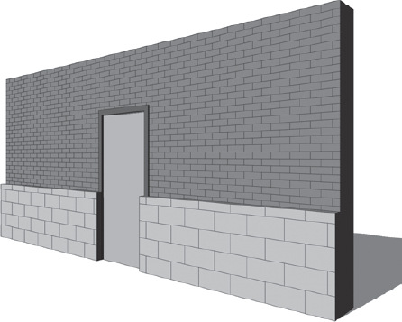
- To place inserts such as doors and windows in a stacked wall, you may need to use the Pick Primary Host tool to switch between subwalls composing the stacked wall. For example, the door shown in Figure 13.32 is outside the upper wall because the main host of the door is the bottom subwall.
FIGURE 13.32 Inserts may not host correctly in vertically stacked walls.
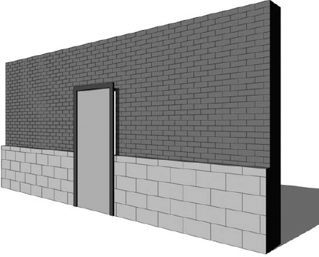
To place the door properly, select it and then click Pick Primary Host from the Modify | Doors tab in the Host panel. Place your mouse pointer over the wall and select the upper subwall (you may need to press the Tab key to select the correct component). The door will then be properly hosted in the upper wall, as shown in Figure 13.33.
FIGURE 13.33 Use the Pick Primary Host tool to adjust inserts in stacked walls.