
Creating a Family Component
Now that we've discussed some of the basic definitions and rules of the Family Editor, we'll talk about the hierarchy of creating a family component. As previously discussed, not all families are created in the Family Editor. Host families, for example, such as walls, floors, and ceilings, are created directly in the project environment. It's possible to create component families in the project environment, but it's important, in most cases, to avoid doing so.
Creating what Revit calls in-place families is often a dead-end process that robs you of hours of otherwise productive time for a number of reasons. First, an in-place family should be used only in cases where the object that you're making is not likely to be moved, rotated, or copied. Any attempt to move, rotate, or copy an in-place family can often have unintended consequences that are difficult to pinpoint. For example, if you model an in-place family and then create copies in your project, they may all initially look the same, but in fact you're copying new instances. So modifying one of the instances is going to leave the others untouched, which can be frustrating if you've copied the instances thinking that later changes would ripple through the project.
Second, each copied instance will schedule independently from the other instances as separate line items. This is often not desirable, as you may want to group like elements together in a schedule.
Finally, there's no way to convert an in-place family into a component family. In some cases, you can copy and paste sketch lines or other 2D elements between the project and family environments. But if you try to copy and paste geometry from the project environment to the Family Editor, you'll get the warning shown in Figure 15.7. The only way to proceed is to start again in the Family Editor.
FIGURE 15.7 It's not possible to copy content from your project to the Family Editor.

The bottom line is that if you're going to use more than a single, highly unique instance in a project or across projects, it's probably best to create the component in the Family Editor, not as an in-place family.
So you need to consider the following criteria before you create a family component, particularly since some of the criteria can't easily be changed (if at all). You'll probably have to start over if you choose poorly. We've also tried to order the criteria for creating a family component from most to least restrictive. Most restrictive means you may have to start over. Least restrictive means you may get away with changing a parameter or value after you've already started the family.
Hosted vs. Nonhosted
![]() The first and most important question you need to ask yourself as you select your template is whether the family is meant to be hosted or nonhosted. If you make the wrong decision here, you'll have to start over to switch between these types.
The first and most important question you need to ask yourself as you select your template is whether the family is meant to be hosted or nonhosted. If you make the wrong decision here, you'll have to start over to switch between these types.
First, keep in mind that hosted objects are meant to cut their host or create an opening or depression. Obviously a window needs to cut the wall that it will go into. Or a fire extinguisher case will often need to create a recess in the wall in which it will be placed. Second, if the component is to be hosted and you're certain that it needs to create an opening in its host, it can only cut one host. For example, a window that is wall hosted may not be hosted by a roof or ceiling.
Want to see a bad example of this? Open the Tub-Rectangular-3D family component in the Family Editor that comes with Revit (Figure 15.8).
FIGURE 15.8 Wall-hosted plumbing fixtures

What's wrong with this picture? Well, first, not all tubs need walls, so you'll have to make another family that has no host in order to place the tub where there is no wall. This seems a bit redundant, because one tub will do.
Second, if you delete a host, all the nested elements are deleted as well. This makes some sense when you delete a wall that contains a window. But it will certainly lead to a lot of frustration if you delete a wall that contains bathroom fixtures!
But what if you want the tub to move with the wall? There's a better way. Simply place the element and select the Moves With Nearby Elements option (Figure 15.9). When the host moves, the component will move as well.
FIGURE 15.9 Moves With Nearby Elements option
![]()
We can't stress enough: stay away from creating hosted relationships between objects that do not require hosting (that do not cut or otherwise modify the host). This discussion brings up an interesting point. Rather than use hosted elements, why not make elements face-based? There are some advantages:
- You don't have to decide on a particular host. Any surface will do: Wall, Ceiling, Top Of Casework, anything that has a face. This is great if the lighting component you're creating needs to cut into a wall, floor, and ceiling!
- A face-based element can cut the face of geometry in both the project and family editing environment. So the light fixture that cuts a wall in a project can cut the face of a piece of casework in the Family Editor.
- Deleting the host will not delete the component. Is this always desirable? Well, maybe yes and maybe no. But what's important is that you have the option if the component is face-based. You won't have the option if the component is hosted.
Finally, one last point with regard to hosting and face-based elements: why not simply model the elements, share the parameters, and then nest? This approach often gives the most flexibility.
Family Category
![]() After you've decided whether you're going hosted or nonhosted, you must choose the correct family category. As mentioned earlier in the chapter, this step is also critical. The reason you need to select the category carefully is because some categories can be switched after the fact, but that is not always the case. This is particularly true when the component has behavior that is specific or unique.
After you've decided whether you're going hosted or nonhosted, you must choose the correct family category. As mentioned earlier in the chapter, this step is also critical. The reason you need to select the category carefully is because some categories can be switched after the fact, but that is not always the case. This is particularly true when the component has behavior that is specific or unique.
For example, lighting fixtures contain elements that allow the light to render once placed in the project environment. Balusters are another example of elements that have specific behaviors built in.
Insertion Point
![]() Now that you've defined the hosting and family category, the rest is pretty flexible. If you choose poorly, you'll probably be able to recover most if not all of your work if something needs to change. But some considerations should come before others, which is why we believe that the insertion point is the next most critical criterion on your list of family creation.
Now that you've defined the hosting and family category, the rest is pretty flexible. If you choose poorly, you'll probably be able to recover most if not all of your work if something needs to change. But some considerations should come before others, which is why we believe that the insertion point is the next most critical criterion on your list of family creation.
The insertion point determines the location about which the family will geometrically flex—not just in plan view but also in elevation. The reference level in the Family Editor directly corresponds to the datum level in your project. Keep in mind that not only does this relate to the visibility of your component in a view, but it also relates to how the component will schedule. This is important for a couple of reasons. First, when the family expands or contracts geometrically, the insertion point will remain relatively fixed.
But second (and often more importantly), the insertion point is the point of reference when two family components are exchanged. This is critical if the “design” family that you've used as a placeholder is being swapped out for something more specific at a later date. If the insertion points are not concurrent, the location of the new family will not agree with the location of the old one.
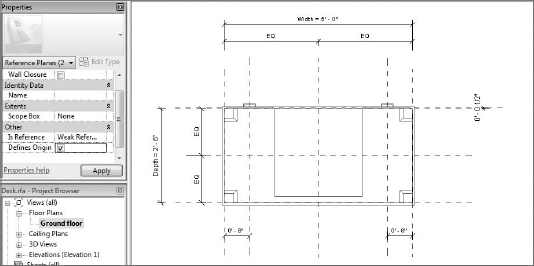
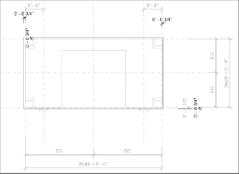
For example, the default Desk.rfa file in the following example has the insertion point located at the center of the object (Figure 15.10). This means the desk will flex about this point. But this is not desirable if the desk, table, or furniture object has a different insertion point that you are about to swap out for this example or if the family needs to flex from a different location.
FIGURE 15.10 Default Desk.rfa family component

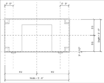
Keep in mind that changing the insertion point is easy. As you would expect, you don't move the geometry to the insertion point. Rather, you simply select two reference planes and then make sure the Defines Origin option is selected. Based on our experience, we recommend that the insertion point for this particular family would best be located at the face of the desk, as shown in Figure 15.11. This would allow the desk to flex with respect to the seating, so that if the desk is larger or smaller you won't have to spend time relocating all the chairs.
FIGURE 15.11 Redefining the insertion point
Reference Points, Planes, and Lines
If you're confident that what you're about to model in the Family Editor will need to flex (have a modifiable length, angle, location, and so on) from within the rules of the family, then it's important that you start modeling the geometry by first creating the rules that will allow the geometry to move.
With few exceptions, you don't want to give parameters to the geometry itself. Instead, you'll want to create the necessary reference planes, lines, and points first. Then associate the parameters to these references and whenever possible test the parameters to make sure the references are flexing properly. Once you're confident the references are flexing, you can build the geometry in context to the references, again testing to make certain that when the references flex, the geometry is flexing as well.
Which reference you use is based on how you want the geometry to flex:
Reference Points These have three planes that can be set to host sketch lines or geometry. You can also use a series of points to control a line or even a spline. Other objects such as reference lines or other geometric surfaces can also host reference points. You can select reference points from the dialog box shown in Figure 15.12.
FIGURE 15.12 Reference points in the Draw dialog box

However, reference points are available only in the categories of certain families: Mass, Adaptive Mass, and Curtain Panel Pattern Based.
Reference Planes These define a single plane that can be set to host sketch lines or geometry. They're best for controlling linear geometric relationships. Reference planes don't have endpoints. This is important because you don't want to use reference planes for controlling angular or directional relationships.
The linear relationships of length, width, and height are perfectly well suited for controlling the geometric parameters of the desk default Desk.rfa family component. All of the geometric options are parallel to one another (Figure 15.13).
FIGURE 15.13 Reference planes controlling the parameters of the default Desk.rfa family
Reference Lines These by definition have endpoints and are great for controlling angular and directional relationships. They can have four points of reference, two along the length of the line (which are perpendicular to each other) and one at each end that is perpendicular to the line.
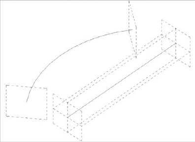
You can also create curved reference lines, but they only have planes that may be used for hosting at each end. There are no references along the curved line (Figure 15.14).
FIGURE 15.14 Straight and curved reference lines
The great thing about reference lines is that because they contain endpoints, they're able to manage angular relationships.
PARAMETERIZING REFERENCE LINES
Here's a simple tutorial for parameterizing reference lines. Don't even try this with reference planes. It would break—because by definition, “planes” don't have endpoints. So when you try to parameterize an angular value between two reference planes, they tend to lose their angular origin. Fortunately, lines have endpoints, so controlling them from an endpoint is far more predictable.
First, open a Generic Model template and draw a series of connected reference lines. If you are deliberate and make them all the same length and angle, it'll save some time. Here's what you should have when you're finished:

Now take a moment and add length and angle dimensions to each of the lines. Parameterize all the length parameters together, and then do the same things for the angles. If you've drawn your reference lines carefully (all the same length and angle), you'll be able to parameterize them by selecting the dimensions all at once. If they're different, you'll need to select each length (and each angle) one at a time and associate with the appropriate parameter. When you're finished, your family should look like this:
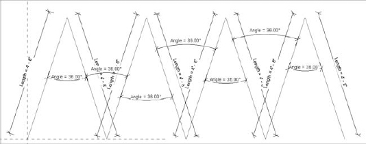
Now comes the interesting part: create a single swept form by picking each of the reference lines together. After you've finished your sweep, you'll realize that when you flex the angular and length parameters, the sweep will remain associated with the reference lines. The following image shows you some of the iterations you can produce with the same family by changing the parameters:
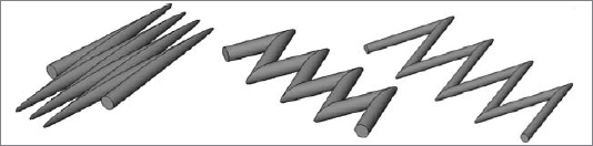
With this technique, you can imagine that modeling accordion panels shouldn't be a problem. You can show the panels as open or closed, driving the individual segment lengths from an “overall” length that is divided among the individual segments.
Visibility Settings
The time it takes for Revit to generate or regenerate a view depends on how much stuff in the view needs to be displayed. One of the great things about Revit is that it automatically assigns the level of detail based on the scale of the view.
When you're building smaller parts of a larger component (or if the elements are not visible in certain orientations), you should assign those elements to only reveal themselves at a certain level of detail (or certain orientations). Doing so keeps Revit from having to manage more information than necessary and helps you keep your views uncluttered. Here's a rule of thumb: once the separate lines that represent something print as a single, merged line, there's little point in having that element display in that view or at that scale. Although this was an entirely intuitive realization when drawing with a pencil (don't draw over the same line twice), unfortunately computers have allowed us to draw beyond a point of diminishing returns.
To see how to fix it, open the default Desk.rfa family, which is fairly well built, but if you look closely, you'll notice that orientation and detail level are not being fully specified. All of the drawer faces and hardware are showing up at every view in every section or elevation.
STARTING WITH EXISTING CONTENT
Let's face it—we've all downloaded content to get a first design pass at a piece of content. Autodesk Seek, Revit City, and the AUGI forums are all great places to start. When you do, take a moment to make sure that the detail level and orientation of detail are appropriate.
In this Desk.rfa family, everything is showing up in every level of detail. This isn't necessarily a big deal with just a few objects. But multiply this by all the other elements that will make up your plans, reflected ceiling plans, elevations, and sections, and you'll notice that your views don't refresh, rotate, print, and export as fast as you'd expect. When this happens, one of the first things you look for is an object in a view that is being shown at a level of detail that is far too high. In some cases the object only prints as a small, black dot. But when you zoom in you'll notice that it's full of detail.
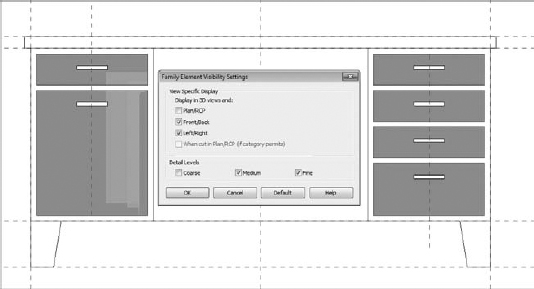
Controlling the detail parametrically is done through the Family Element Visibility Settings dialog box (Figure 15.15).
FIGURE 15.15 Family Element Visibility Settings dialog box

Notice that the box for the Plan/RCP option is unchecked. This is appropriate for the desk, because little more than the surface of the top of the desk needs to show up in plan. The legs, the hardware, and even the faces of the drawers don't need to show up in plan.
But what about the elevations? By turning off the Thin Lines option, you can see that all the geometry is showing up at every level of detail in a view that's set for ⅛″ = 1′-0″ [1:100] (Figure 15.16).
In these cases, Zoom To Sheet Size is your friend. Figure 15.17 shows the same desk in elevation when that option is active. It's obvious that you'd never need that level of detail at that scale.
FIGURE 15.16 Lines beginning to merge

FIGURE 15.17 Zoom To Sheet Size
It should be apparent that there's far more detail than necessary for this view and the solution is simple. Set the drawer faces to show up at a Medium detail level or finer, and set the hardware to only show up at a Fine detail level. Do this to all your content and performance should noticeably increase (Figure 15.18).
FIGURE 15.18 Adjusting the detail level
Materials
Materials are crucial to a family. But what is possibly more important is the Shading setting and the Transparency value of the material, because they communicate much about the intent of your design in the early stages (Figure 15.19).
FIGURE 15.19 Shading and Transparency settings in the Materials dialog box

In addition, material options are often not easily created in Revit. Yes, a family can have a material parameter. But expressing many different parameters for visualization purposes is probably left to the visualization specialist who understands the subtleties of creating an emotive image, not just a “rendering”—and it's unlikely they'll be using Revit to iterate or emotively visualize your design.
![]() Beyond visualization however, materials in Revit are used for a host of other things. Graphic representation in construction documents and material take offs are two examples. If the materials in your families are something you will need to schedule or view graphically it's a good idea to define them.
Beyond visualization however, materials in Revit are used for a host of other things. Graphic representation in construction documents and material take offs are two examples. If the materials in your families are something you will need to schedule or view graphically it's a good idea to define them.
Multiple materials can be assigned to a family. They are assigned based on model solids, so if you have multiple solids (sweeps, extrusions, etc) each individual one can be given an individual material.
You have two options to define a material within a family both being handled in the solid's object properties shown in the Property Pallet. By default, the material is set to <By Category>. Select this option and you can change the material to any material shown in the Material dialog box. Or make a new one. This is a great use for the family if you know the material is not going to change. If you know that your casework is not going to be anything but blonde maple go ahead and set the material with in the family. Your other option is to use the tiny little button on the right of the Material field in the Properties Pallet to define a new parameter. In this case, you can call the material something like ‘casework material’ as a property. If you were to use this same parameter for all your casework families, once placed in the model you can change that material via the Material dialog box and it will update all your casework families (using that parameter name) at once.

Dimensions
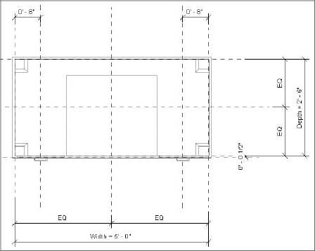
As mentioned earlier, dimensions are useful for controlling the geometry parameters of your families. It's best to keep the dimensions outside of Sketch mode. Let's use the desk as an example. In plan view, you can see all the reference planes and dimensions (Figure 15.20).
FIGURE 15.20 Parameterized dimensions
Now select the top of the desk and select the Edit Extrusion option. What you'll find are dimensions to the edge of the desktop (Figure 15.21).
FIGURE 15.21 Dimensions inside Sketch mode
These dimensions are “inside” the Sketch mode of the desktop. This is fine in the sense that they'll work. But as a best practice, don't put parameterized dimensions inside Sketch mode. The reason is that when you complete the sketch, the dimensions will be hidden. Then when you're trying to troubleshoot or modify parameters, you won't be able to easily find the corresponding values in the model view.
Object Styles and Subcategories
Revit has predefined a number of hardwired family categories. These categories can't be modified or added. As mentioned earlier, they define how elements display, schedule, export, and so on. But within the default object categories, you can create subcategories for model, annotation, and imported objects (Figure 15.22).
FIGURE 15.22 Object Styles dialog box
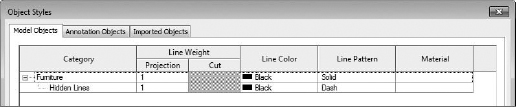
Although you can use subcategories to control the visibility of some part of the whole component, keep in mind that the detail level and visibility settings already manage visibility. The subcategories are most important when you're exporting your project, because each category and subcategory is permitted its own CAD layer (Figure 15.23).
FIGURE 15.23 Export options for categories and subcategories

So if your project is being exported to CAD in such a way that you'll need to associate objects with granular layer settings, creating and assigning subcategories to elements is necessary. It's best not to rely on subcategories to manage visibility.
Type and Instance Parameters
![]() Many users new to Revit start to panic when they have to select between a type and an instance parameter for the first time. Don't panic. Keep in mind that you can change these two items after you set them initially. Whenever you reload the family into the project environment, the previous settings will be overwritten.
Many users new to Revit start to panic when they have to select between a type and an instance parameter for the first time. Don't panic. Keep in mind that you can change these two items after you set them initially. Whenever you reload the family into the project environment, the previous settings will be overwritten.
The key difference between the two is that modifying a type parameter always modifies all the other components of the same time. Think of a type as a set of identical elements. Change one item in the set, and all the other items of that type in the model change to match. Door sizes are a good example of this. Doors come in standard sizes: 32″, 34″, 36″ [80 cm, 85 cm, 90 cm]. On the other hand, an instance parameter only modifies the components that you have selected. A good use of an instance parameter would be the fire rating on a door. Not every 36″ [90 cm] door will be fire rated, so you'll need to identify which ones individually. Figure 15.24 shows the parameters of the default Desk.rfa family.
FIGURE 15.24 Parameters of the Desk.rfa family
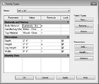
You can tell all these parameters are type parameters because any time you have an instance parameter, the text “(default)” appears after the parameter value. In this case, it's likely important that the dimensions are type parameters. You don't want users to create random or arbitrary Depth, Height, and Width values.
On the other hand, each new option can create a lot of new types. By default, loading a family into your project will also load all the types. If you want to create the potential for many types but be selective about which types are loaded, you can use a type catalog to load only specific types.
USE NESTING AND PATTERNS FOR QUICK TURNAROUND
Geometry from one family can be loaded into another family. This process is called “nesting,” and it allows you to create a single element that will be used many times in one or more families. This is much more desirable than creating an element and then grouping and copying it around the same family. Become accustomed to using nesting whenever possible because it'll save you a lot of time when your design changes.
First, it's much easier to change and control the location of a nested family. The nested family can also have references and parameters that can control it when nested.
But more importantly, the nested family can be controlled by a “Family Type” parameter, which will allow you to switch between nested families as another parameter. This feature is incredibly powerful for creating design iteration within families that are in your projects.
Second, as soon as you have a reasonable representation of your family, get it in the project. Don't be afraid to start simple and update it later. Users sometimes obsess about the details and hesitate to load the family into the project until it's “perfect.” This tendency can hold up a project. So get the idea in the project first and make it ideal later. Just take care about the insertion point so that when you modify it (or exchange it with something more detailed) its relative location will remain the same.
Finally, look for opportunities to use model patterns in lieu of geometry. Doing so is important in the project environment, but it's also important (and often overlooked) in the Family Editor. Model patterns graphically regenerate far faster than small geometric parts and pieces.