
Stairs In and Out of the Box
Using in-the-box techniques means you're using the built-in functionality of the Stairs tool to create conditions that may not have been originally intended by the factory. In most cases you'll be using the functionality to create conditions that are common in complex stair conditions.
Sometimes there's no way to anticipate every unique and sculptural design condition. In these cases, we'll show you techniques that aren't exactly using the Stairs tool as prescribed but the results will geometrically resemble stairs (and their railings).
Understanding the Revit Stairs Tool
![]() A key concept in making the best use of Revit is to not get hung up in how elements and tools are named or labeled. For example, a great way to create a sloped ceiling in Revit (since the Ceiling tool cannot be sloped) is to use the Ramp tool. With ramps, you can create all kinds of sloped surfaces—just make your ramp out of ceiling tiles or gypsum board. This same concept applies to stairs—don't overlook the nosing profile family as a device for creating interesting shapes that complete the tread, because the shape of the nosing is not limited to traditional nosing profiles. Any shape that needs to extend beyond the face of the tread is fair game to model with the nosing profile family. Just remember that you're limited to a single profile per tread and stair run (Figure 16.41). You'll also want to pay particular attention to the insertion point of the nosing profile because the intersection of the reference planes coincides with the top of the tread and the face of the riser.
A key concept in making the best use of Revit is to not get hung up in how elements and tools are named or labeled. For example, a great way to create a sloped ceiling in Revit (since the Ceiling tool cannot be sloped) is to use the Ramp tool. With ramps, you can create all kinds of sloped surfaces—just make your ramp out of ceiling tiles or gypsum board. This same concept applies to stairs—don't overlook the nosing profile family as a device for creating interesting shapes that complete the tread, because the shape of the nosing is not limited to traditional nosing profiles. Any shape that needs to extend beyond the face of the tread is fair game to model with the nosing profile family. Just remember that you're limited to a single profile per tread and stair run (Figure 16.41). You'll also want to pay particular attention to the insertion point of the nosing profile because the intersection of the reference planes coincides with the top of the tread and the face of the riser.
FIGURE 16.41 Custom nosing profile
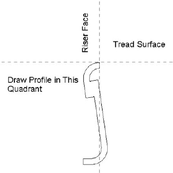
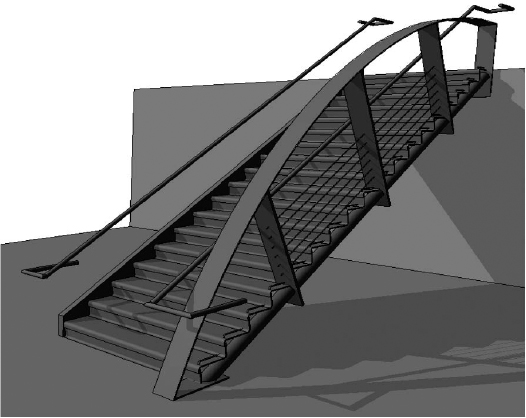
Figure 16.42 shows an example from a real stair that was designed to have each tread fabricated from a single plate of steel and then rolled to form the face of the riser above it. Here, each of these treads can be welded behind the lip of the tread above it. It's a fairly elegant idea that can be accomplished by using a custom nosing profile to create the appearance of a continuous tread (Figure 16.42). Look closely and you can see where the actual tread ends and where the nosing profile begins. Final linework can be adjusted or hidden (if necessary) when you're creating the details.
FIGURE 16.42 Continuous tread and nosing profile
Make sure that if you're using a custom profile to represent both the nosing and the riser that you set Riser Type to None in the stair type properties. If you don't, the profile won't be assigned correctly; it will overlap with the default riser. Figure 16.43 shows these stairs in their final form using our custom profile. As for custom railing conditions, we'll go into that later in this chapter. If you'd like to investigate this stair further, it's in the Chapter 16 folder on the book's companion web page and is called Henrys Stepp.rvt.

UNDERSTANDING THE STRINGER
Stringers in Revit are good for creating a number of standard residential (wooden) or steel (commercial) conditions. What's important is that the default stringers in Revit can only be rectilinear in shape and may be positioned to either side of the stair (left and right) or the middle. If you want a custom shape, you're out of luck if you're using the default stringer. When creating a custom stringer profile (left, right, middle, or otherwise), use the Railing tool (Figure 16.44). The stair will host this railing containing the custom stringer profile (or just the custom profile, with no handrail).
FIGURE 16.44 Use the Railing tool to create a custom stringer profile.
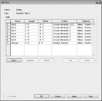
Notice in Figure 16.44 that the last profile is not part of the traditional portion of the railing. Instead, this profile is used to indicate a custom stringer profile (Figure 16.45). But it's been assigned to the railing in order to maintain a particular relationship to their stairs.
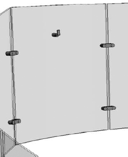
In Figure 16.46, we've isolated the railing from its stairs in order to illustrate the finished railing: the handrail, two glazed and continuous panels, and the custom stringers.
FIGURE 16.46 Completed railing profile

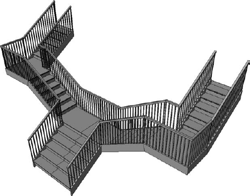
This railing with a custom stringer profile is perfect for a multitude of stair conditions, straight or curved or even a combination (Figure 16.47). This technique finishes off the stair nicely and exposes the structure in interesting ways.

Although the stringer usually occurs to the left or right of the treads, this is certainly not always the case. In some situations you'll want to create a middle stringer using a custom profile. Just remember that this will be a railing that will be hosted by the stair and may not even contain a handrail, just the profile for the stringer (Figure 16.48). In this case, the railing is still being hosted by the stairs—it's just that there's just not any railing geometry above the tread.
FIGURE 16.48 Custom middle stringer profile

CUSTOM CONDITIONS AND SHAPES
Straightforward tread shapes can be pretty boring, so let's move on to custom tread conditions. In situations where you need to be a bit more inventive, you're going to create a custom baluster. This technique can either create a custom support element for the default treads or it can indicate the actual tread.
But instead of the baluster being vertical, it's going to be horizontal. This horizontal baluster will be used in conjunction with the default tread. This baluster may even completely envelop the tread.
First, we need to discuss a few rules for creating an interesting tread support for the default tread (Figure 16.49):
FIGURE 16.49 Baluster as tread support
- Not every baluster needs a railing. If your baluster support isn't going to be a part of the “real” railing, just create another “railing” that is hosted by the stairs. Sketching another path for your custom railing that only contains the tread support baluster can accomplish this in a few steps. Another technique is to copy an existing railing, then paste it to the exact same location and change the type to your custom supporting baluster.
- The Baluster Family category needs to be used for the component that will act as the tread support. Otherwise, it can't be associated to the railing.
- If you have a complex support element, it may be helpful to model the desired support element as a generic family. When you're finished, nest this generic element into the baluster family. You may want to do this because the baluster templates have hardwired reference planes and parameters (which is fine if you're making a baluster that needs to geometrically flex). But in this case, we've found that these reference planes and parameters may cause your baluster to fail when you load it in the project as a result of these parameters flexing. By modeling the geometry elsewhere and nesting it, you avoid this hassle since it moves as a single component.
- Designating the level of detail is crucial. Assigning Coarse, Medium, or Fine levels of detail leads to much faster graphics regeneration, view panning, and model rotation. So if you're nesting one component into another family, the detail that you're assigning at the deepest level will be respected through nesting (Figure 16.50).
FIGURE 16.50 Single component that will be used as a tread support
Once the component is complete, you can nest it into a baluster template, as shown in Figure 16.51. If necessary, it's also possible to parameterize the dimensions in the nested configuration.
FIGURE 16.51 The generic model nested into a baluster family

The completed stairs are shown in two different configurations in Figure 16.52. Many configurations are possible once you correctly define a single stair type. If you'd like to investigate this stair further, it's in the Chapter 16 folder on the book's companion web page and the file is called _Angled_Support_Stair.rvt.

Note that a custom baluster support might be modeled to contain the real balusters that are intended to support railings. This can simplify and shorten modeling time. In the example shown in Figure 16.53, the baluster support geometry also contains the railing elements on both the right and left side. If you'd like to investigate this stair further, it's in the Chapter 16 folder on the book's companion web page and the file is called Support Tread.rvt.
FIGURE 16.53 Complex baluster support with balusters

The previous support baluster can be brought together with a custom profile for the center stringer, handrails, and glazed panels (Figure 16.54). You can download this example from the Chapter 16 folder on the book's companion web page and the file is called Center Baluster Support.rvt.
FIGURE 16.54 Complex support with balusters

CONTROLLING THE BALUSTER SUPPORTS
Don't forget to control the number of baluster supports per tread. Revit has an easy way to accomplish this through the railing option Use Baluster Per Tread On Stairs.
Once you've begun to experiment with creating balusters as tread supports for stairs, you'll notice you have options for making more complete and finished conditions.
Start and end posts are useful and can help complete the structure of your custom railing and baluster system, particularly if you want to properly anchor and connect your custom stair and railing. The example in Figure 16.55 uses only start and end posts to anchor the custom railings and stair structure. It builds on the previous example of using a baluster as a support element for a tread.
To finish this stair, you need to create start and end posts that anchor the stair. As with the previous handrail join exercise, you'll want to model the bulk of the custom stair with the custom railing. Then you'll export the stair parts for importing into the baluster template (or the generic model template that will be nested into the baluster template).
FIGURE 16.55 Baluster as a support element
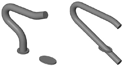
Figure 16.56 shows the results after the start and end posts are modeled.
FIGURE 16.56 Finished start and end posts with a connection
When it all comes together, the results can be elegant and interesting. All of this is available through the default Stairs tool. You can download this stair from the Chapter 16 folder on the book's companion web page; it's called Tube Stair.rvt.
Now let's go one step further. There's no reason that the baluster support element needs to exactly conform to the shape of the tread. And there's no reason that the support element can't contain the actual baluster that is intended to support the handrail.
Take a look at the support element in Figure 16.57. Not only does it contain the support element, but the support element has been modeled to exceed the shape of the tread that will be modeled by the Stairs tool.
FIGURE 16.57 Support and baluster as a generic model

Keep in mind that we've modeled the support element as a generic model and then nested it into a baluster post template (Figure 16.58). Again, this keeps the baluster together so it's not affected by the built-in reference planes and parameters.
Once this custom baluster post is loaded into the project, simply associate it with the stair and its railings. Remember to select the One Baluster Per Tread option. When finished, the default tread is simply an inlay to the more complete tread support (Figure 16.59). In more complex conditions, it may be desirable to envelop the entire tread with the support geometry. Doing so will allow you to create complex tread shapes that are not dependent on the default tread and use the functionality of the Stairs and Railing tools to properly locate, rotate, and elevate each of your custom treads. If you want to examine this stair further, check out the file Curved Tread Support.rvt in the Chapter 16 folder of the book's companion web page.
FIGURE 16.58 Baluster and support nested into a baluster post template
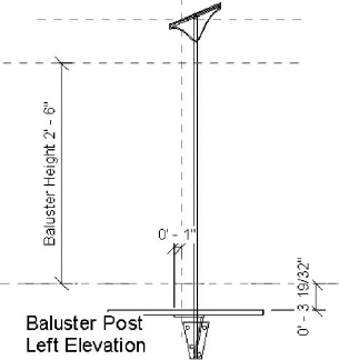
FIGURE 16.59 Finished stair with integrated baluster and support
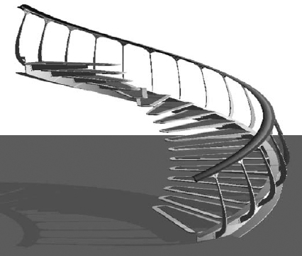
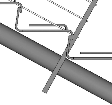
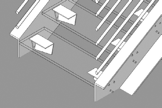
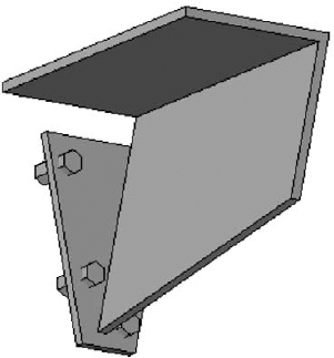
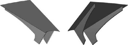
Figure 16.60 shows an example using this technique. The tread support elements have been modeled using blends in order to sweep under the metal plate while changing direction from vertical to angle. This will accommodate the angled pipe rail that will support the stair.
FIGURE 16.60 The top and underside of tread support
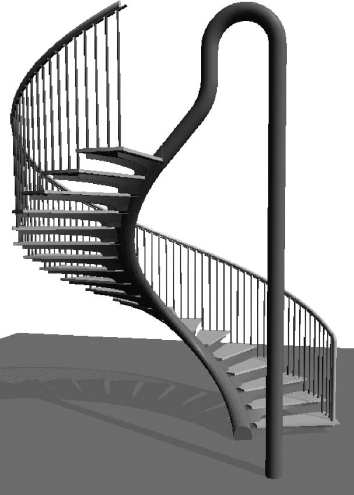
Treads come together in a particularly interesting stair and railing configuration. There is obviously a more conventional outer railing for this stair. But the inner railing doesn't have any elements that occur at hand height. The entire inner railing exists to support the baluster supports (that in turn support the default treads). The end post is being used to anchor the entire structure through the second level. You can find this example, Highlights.rvt, in the Chapter 16 folder of the book's companion web page. Figure 16.61 shows the finished stair. Note that the large structural element is actually a baluster that's been designated as the end post.
FIGURE 16.61 Completed stair with large end post
Stairs Outside the Box
As we approach out-of-the-box techniques, the goal is to create elegant stairs, knowing that the metadata may not correspond to the geometry. This is usually the only option to complete a design within BIM where there's no in-the-box technique and without having to resort to only 2D representation. These techniques take an extra level of care. The metadata—the information part of BIM—isn't being coordinated properly, so you'll want to take particular care with regard to tagging and scheduling.
Let's start with the stair from the previous section (Figure 16.62).
FIGURE 16.62 Finished stair with integrated baluster and support
While the railings on the left side of the image seems pretty straightforward, the curved railing on the left may seem a bit challenging, the three balusters inside the curved element are perpendicular to the run of the stair, and the cable starts and stops before completing the run—which is the default condition.
This example nests geometry modeled in the generic family template and then nests that geometry into a baluster post template. The baluster is then assigned as the start post to create the entire railing. The nice thing about using the start post is that whenever you create the stair, the “railings” are automatically added, even if you create a multistory stair condition.
Once again, there are a few steps to follow, with which by now should be rather familiar.
First, model what you can with the out-of-the-box tools. Even if you can only model the treads, this will help give you context to the rest of the system; then export the treads from a 3D view and import it into a generic model family. In this case, everything that can be modeled as the stair is shown in Figure 16.63.
FIGURE 16.63 Completed stair before exporting

After exporting this stair in 3D and importing it into the Family Editor, you can model your design in context with exactly how it will be used. Figure 16.64 is the resulting form that will be assigned to the stair's railing as a start post.
FIGURE 16.64 Baluster post as a complex railing

This is a valuable technique for creating complex and difficult-to-predict railings for stairs. The important part of this technique is to use the out-of-the-box Stairs tool to model whatever is easily possible for context. Once again, here are the steps:
- Export the stair in 3D.
- Import the exported file into a generic model family.
- Model your complex railing design in context with the imported 3D (keeping in mind that reference planes are helpful).
- Nest the finished family into a baluster post family.
- Associate this baluster family as the start post for the railing.
Here's another example of using this technique to overcome an otherwise complex condition that simply could not be created using the default Stairs and Railing tools. The stair in Figure 16.65 is modeled with the default tools: Stairs, Baluster, and Railing. This creates all that is necessary for modeling the wire cable net that will be used to complete the stair.
FIGURE 16.65 Parts of default stairs

Once this geometry is exported, it's ready to be used as context for modeling the cable net that will be assigned as the start post for the stair (Figure 16.66). If you want to study this stair and railing further, check out the file Cable Stair.rvt in the Chapter 16 folder of the book's companion web page.
Now we'll talk about other challenging configurations. In many cases, it's not the parts that make up the entire stair that is the challenge. Often it is the overall configuration that vexes people (like creating the three-run stair we discussed earlier).
FIGURE 16.66 Cable net with stair and railing
A solid spiral wall to be used as a railing or a support element can easily be created in the Family Editor and then associated with the stair as a start post. Of course, this geometry could also be created as an in-place element. But then you'd lose the advantage of being able to quickly and easily relocate the stair in your project (or create a multistory condition).
In Figure 16.67 you can see the default tread with a baluster being used as a support element. What's interesting about this configuration is that rather than being configured as a circular stair, the path is made of two concentric arcs.
FIGURE 16.67 Baluster used as a support element

Rather than create this as an in-place family under the stair, we'll model the swept blend as a baluster post in order to associate it with the beginning of the custom baluster. In order to make sure that we have the path exactly right, we'll copy the path of the custom railing that's associated to the support baluster (Figure 16.68).
FIGURE 16.68 Copied path of the custom railing

Now you can use this path as you create each of the blended sweeps (creating only one swept blend per path). In this case the blends are being modeled so that there's a 3″ gap between the undersides of the default treads. The final swept blend in shown in Figure 16.69.
FIGURE 16.69 Finished swept blend

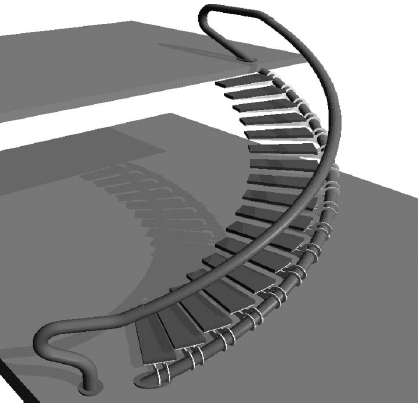
Figure 16.70 shows what you get when it all comes together. The swept blend has been created in a baluster template. This baluster is then loaded into the project environment and associated with the railing that contains the overall support baluster. This is also useful if you have to create walls that need to follow either side of a stair. If the condition exists only once, you may opt to create this in-place.
FIGURE 16.70 Finished stair condition
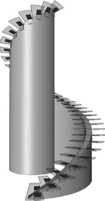
But if it occurs more than once or might be rotated and relocated (as well as occur on many levels), we recommend that you create this as part of the stair and railing definition. Then it'll be easier to maintain relationships throughout the project. To investigate this stair, download the Concentric Stair.rvt file from the Chapter 16 folder of the book's companion web page.
Another condition that results in a lot of confusion is creating a circular run that ends aligned from where it begins. This is also quite easy to accomplish once you understand the proper steps.
First, as you start to create the circular run, you'll notice the number of required treads. In the case of the default stairs and default template, 18 risers are required. Start by creating half that number, or 9 (Figure 16.71).
FIGURE 16.71 Sketching half the required risers

Once you've created the first half of the stairs, rotate and mirror the nine risers (Figure 16.72).
FIGURE 16.72 Align and mirror half the risers.

Now here's the tricky part: Sketch the remaining boundaries manually. In other words, don't elect to finish the run and think that Revit will automatically complete the boundary for you (which works with more conventional configurations; see Figure 16.73).
Now you're ready to finish the stair sketch with the confidence that the end of your stair is aligned with where it begins (Figure 16.74). To study this stair, download the Curved and Aligned Stair.rvt file from the Chapter 16 folder of the book's companion web page.
FIGURE 16.73 Finished stair boundary

FIGURE 16.74 Finished aligned and circular stair

Another type of stair that creates a lot of confusion is a stair with split runs. In other words, it may start as one run, but then it splits (typically at the landing) and becomes two separate runs. The challenge is that many users will create the first stair as a complete run. Then they will create a shorter run from the landing to the second level. If only it were easier. Well, it is!
Simply create half the stair and then mirror the results. Although this might create a line along your first run, the line can be hidden, and in the long run, the stair will be easier to modify and update. So let's get started:
- The entire stair is going to be 3′-0″ [1 m] wide, but the first run is going to be 6′-0″ [2 m] wide. The shape of the sketch is shown in Figure 16.75.
FIGURE 16.75 Half the split stair

- Once you finish the stair, edit the railing as shown in Figure 16.76. This will get rid of the railing through the middle of the landing and between the first run.
FIGURE 16.76 Editing the sketch of the railing

- Now finish the stair and mirror the results. That was easy enough! But now you have to get rid of the default stringer that associated with the stairs (Figure 16.77).
FIGURE 16.77 Remove the default stringer.

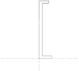
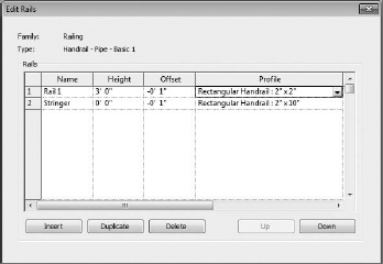
- Edit the properties of the stairs and remove both the left and right stringers. Then create a profile of the same dimensions and associate it with the railing. But rather than create a new profile, make things easy on yourself by duplicating the Rectangular Handrail profile that you already have in your project. Be sure to also modify the type properties of the handrail profile (Figure 16.78).
FIGURE 16.78 Modified handrail type

- Now associate this profile with the handrail that is associated with the stairs, as shown in Figure 16.79.
FIGURE 16.79 Adding the handrail profile
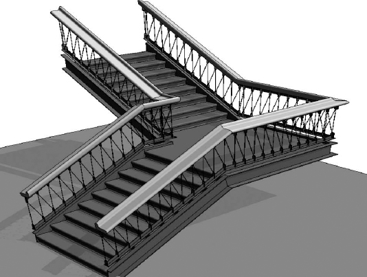
The custom stringer profile now exists as part of the railing definition. Now you have a split run stair that can be easily modified if the design changes (Figure 16.80). This stair can be downloaded from the Chapter 16 folder of the book's companion web page; the file is called Split Run Stair.rvt.
FIGURE 16.80 Finished split run stairs
Now let's put it all together. When it comes to feature stairs, few stairs are as immediately recognizable as the glass stairs and walkways that have been designed for Apple by Bohlin Cywinski Jackson (Figure 16.81). Although these stairs seem incredibly challenging, there's very little about the Apple stairs that can't be modeled out of the box!
FIGURE 16.81 5th Avenue Apple stair in New York

Even though the stairs are very sculptural, there are quite a few repetitive relationships that are easily identified and defined. Of course, what doesn't strictly conform to the rules of the Stairs tool will have to be modeled elsewhere. First, let's model the treads and landing. We're assuming some dimensions since we don't have the actual drawings or measurements to work from: 2″ [5 cm] thick, 6′-0″ [2 m] wide, and a 4′-0″ [1.2 m] interior radius (Figure 16.82).
FIGURE 16.82 Finished tread configuration

A small support “pin” is used to support the treads. One pin per tread supports the inner portion of the tread, but two pins per tread support the outer portion (so right away we'll have to create two separate handrail types for the stair). Figure 16.83 shows the pin family.
FIGURE 16.83 Support pin as a baluster

With this in mind, we're able to place the pin as a baluster after modeling it as a generic model and then nesting it into a baluster family template (not a baluster post), which will allow it to conform to the elevation of the landing. Since the pin is so small, it is also given a “fine” level of detail assignment so it doesn't show up unless the view is set to Fine.
As just mentioned, two handrail types are needed, since they will host different baluster definitions. The inner handrail has one pin support per tread, whereas the outer handrail has two pin supports per tread (Figure 16.84).
As for the start and end posts, two families are needed: one for the start configuration and another for the end. They include the horizontal extension beyond the end of the railing sketch. Once you've added these posts, the stair really starts to come together (Figure 16.85).
FIGURE 16.84 One and two pins per tread with handrails

FIGURE 16.85 Treads, support balusters, and railings

This concludes the portion of the stair that can be modeled out of the box. Export this 3D context for the remainder of the stair, which will be modeled as a generic family and then nested into a baluster post and assigned as a start post. There's a third railing in this stair (which contains no railing profile). This “invisible” railing is hosted by the stair and creates the remaining elements, as shown in Figure 16.86.
FIGURE 16.86 Glazed panels with connections
Two swept blends form the upper and lower glazed and curved panels, and a regular sweep forms the panels at the landing. At the same time, a single extrusion forms the center, glazed cylinder. When all this geometry is modeled, a single void (in plan) is extruded vertically and creates all the discrete panel separations at one time.
The panel supports and the actual balusters that will support the railing are modeled elsewhere and then nested into this family. This approach will allow the object to be quickly updated from a single location. Keep in mind that the handrails in the project will be used to host the baluster “pins” (one or two per tread); the handrail supports will be nested into this family. Each panel has a single baluster element (Figure 16.87).
FIGURE 16.87 Final geometry before nesting into baluster family

Now you're ready to associate this baluster post with a center railing (which contains no handrail). A couple of details are shown in Figure 16.88.
FIGURE 16.88 Completed stair and details

Figure 16.89 shows the finished stair. Yes, there's a lot more to the stair than this: the platform, elevator, landing, and so on. At the end of the day, there's nothing to keep you from modeling the entire stair in the Family Editor and then placing it in the project as a generic model. In some cases, this is exactly the kind of modeling control that complex and sculptural stairs need. Are they stairs? No, they're probably more like inhabitable sculpture. And trying to design sculpture in a spreadsheet is harder than just modeling what you want in the Family Editor. But what about “parameters,” you ask? Well, sometimes defining the parameters takes more time than making the change manually in one place and then reloading the results into your project. If you're interested in downloading this stair, it's in the Chapter 16 folder of the book's companion web page; the file is called Apple Stair.rvt.
FIGURE 16.89 Completed stair, panels, and core

![]() Real World Scenario: IMPORTANT BEST PRACTICES
Real World Scenario: IMPORTANT BEST PRACTICES
Here are some best practices to consider with regard to creating complex stairs and railings:
- Don't forget to nest your family components whenever possible and appropriate. This will keep the component together when associated with some other template that contains hardwired parameters and reference planes. It'll also save you and your team a lot of time during design changes and iteration.
- Don't struggle with creating the stairs in this chapter. If you get stuck, you can download the sample stairs from this chapter and use them for a starting point when creating your custom stair. Just remember it's usually easier to build and test a custom stair or railing in a sample project first. Then copy and paste or use Transfer Project Standards to get the custom stair or railing from the test project to your actual project. Download sample files for this document at the book's web page. You'll probably want to copy your custom stairs and railings in an easy-to-access project that contains row upon row of finished and polished examples (since they can't be kept as family components).
- The level of detail and visibility is crucial if you care about graphic refresh times and printing. As you model the components of your custom stairs and railings, assign appropriate orientation and level of detail (Coarse, Medium, or Fine). You'll notice a difference when you pan and rotate your model.
- Take care to filter schedules. Using a curtain wall as a railing may have certain advantages, but you also want to make sure that your schedules are accurate.
Overall, be careful when reaching into your bag of tips and tricks! You need to weigh the cost of implementing a new process against the cost of doing what's familiar. Make sure that you're maintaining a balance between predictability and efficiency. There are frequently two extremes that you need to avoid:
- The first error involves doing what is highly predictable but not very efficient. In other words, most people will grasp the solution that you intend to implement; they'll fully understand the technology and technique. But they'll also quickly realize that managing design changes and iteration will be highly manual and time-consuming. And the rest of the team will doubt your leadership and understanding of the technology and processes.
- The second extreme is that you'll manage to create a highly efficient uber-solution, but one that is not very predictable to the project team (much less a recently introduced outsider). In other words, it'll almost be too efficient. Only you or perhaps a few team members will understand what you've created. Everyone else on the team will resist making any changes to your creation out of fear that they'll break it.
So, what's important with creating interesting and innovative stairs and railings is that you manage to strike a balance between these two extremes. Just remember these four simple characteristics:
Beneficial Not just to you, but to the project team.
Efficient Implementation and changes that are fast and predictable.
Elegant Understood by the team and by any last-minute new members.
Repetitive Can be used on many projects.
If you can't remember these guidelines, the handy acronym of BEER should help. When you are not sure which solution is the best one to follow, your team will tend to gravitate to whatever allows them to have a beer at the end of the day.
In other words, whatever allows them to decompress, reenergize, and come back to work the next day refreshed, focused, and enthusiastic will ultimately win out. And keep in mind that this principle isn't just important to stairs and railings or Revit or BIM; it's important to having an interesting life.