Exploring Other Editing Tools
A range of other editing tools are available in Revit, and we'll cover them in subsequent chapters when they're used in specific operations; however, there are a few tools you should know about now because they are generic tools you can put to immediate use on any project.
Using the Join Geometry Tool
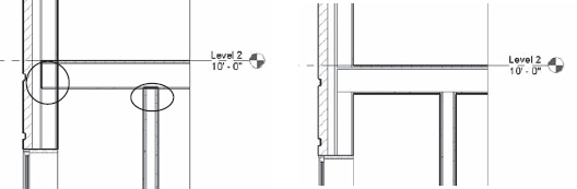
Joining walls to floors and roofs creates clean-looking drawings, and Revit will attempt to create these joins automatically; however, in some cases, elements don't look right until they are explicitly joined. This is where the Join Geometry tool comes into play. This tool creates joins between floors, walls, ceilings, roofs, and slabs. A common use for this tool is in building sections, where floors and walls may appear overlapped and not joined. Figure 3.20 shows a floor intersecting with some walls that aren't joined. Using the Join Geometry tool, you can clean up these conditions nicely.
FIGURE 3.20 Intersections at Level 2 have been joined.
You might notice that some joins—especially in a view set to the Coarse detail level—contain a thin dividing line between two elements. This is usually because the two elements you joined consist of differing materials. Ensuring consistent material application will give you increased graphic quality in your project views.
You should also be aware that joining large host elements to many other elements may cause degraded model performance. One way to avoid this is to apply a black solid fill to elements in the cut plane of your coarse sections and avoid overall manual joining; then selectively join for medium and fine views.
Using the Split Face and Paint Tools
Occasionally you may need to apply a thin material to the face of an object without making a new type of element. You may also need to divide an overall surface into smaller regions to receive different materials. Revit provides the Paint tool to apply materials and the Split Face tool to divide object surfaces. With the Paint tool, you can apply alternative materials to the exterior faces of walls, floors, roofs, and ceilings. This material has no thickness, but you can schedule it with a material take-off schedule and annotate it with a material tag. A typical use case for these two tools is the application of a carpet or thin tile to a floor. See Chapter 14, “Floors, Ceilings, and Roofs,” for a detailed exercise on this topic.
Copying and Pasting
Copying and pasting is a familiar technique used in almost all software applications, and Revit provides the basic features you'd expect (Ctrl+C and Ctrl+V). It also has some additional time-saving options that are specific to working on a 3D model.
To copy any element or group of elements to the clipboard, select them and press Ctrl+C. To paste, press Ctrl+V. In the majority of cases, Revit pastes the elements with a dashed bounding box around them. You then determine where to place the elements by clicking a point to define its final position. In the Options Bar you will find a Constrain option that when clicked will only let you define the location of the pasted content orthogonally to the original elements.
EDIT PASTED
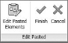
Immediately after you select a point for the location of the pasted content, you will find a new panel in the ribbon called Edit Pasted (Figure 3.21). You can click Finish to complete the pasting action or start another command. If you are unsatisfied with the pasting action, select Cancel.
FIGURE 3.21 Additional actions are available when pasting elements.
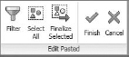
If you select Edit Pasted Elements, a special mode will be started with the Edit Pasted tools appearing at the top left of the active window (Figure 3.22). In this mode, only the pasted elements are editable. You can use the Select All or Filter button to refine those elements within the pasted selection. When your edits are completed, click the Finish button.
FIGURE 3.22 Edit Pasted mode allows additional modification of pasted elements.
PASTE ALIGNED
If you need to paste elements with greater location control, Paste Aligned offers options to make the process simple and efficient. These options allow you to quickly duplicate elements from one view or one level to another while maintaining a consistent location in the X-Y coordinate plane. After selecting elements and copying them to the clipboard, find the Paste button in the Clipboard panel, as shown in Figure 3.23.
FIGURE 3.23 Paste Aligned options

Five options are available when you click the Paste drop-down button, in addition to the Paste From Clipboard option. Depending on the view from which you copy and what kinds of elements you copy, the availability of these options will change. For example, if you select a model element in a plan view, you won't have the Aligned To Selected Views option. These options are as follows:
Aligned To Selected Levels This is a mode you can use to quickly paste copied elements to many different levels simultaneously. When you select this option, you choose levels from a list in a dialog box. This is useful when you have a multistory building design and you want to copy a furniture layout that repeats on many floors and selecting level graphics in a section or elevation would be too tedious.
Aligned To Selected Views If you want to copy view-specific elements such as drafting lines, text, or dimensions, this option allows you to paste them by selecting views from a list of views in a dialog box. In the list available for selection, you don't see levels listed but rather a list of parallel views. For example, if elements are copied from a plan view, all other plan views are listed. Likewise, if you copy from an elevation view, only elevation views are listed.
Aligned To Current View This option pastes the elements from the clipboard into the active view, in the same spatial location. For example, if you copy a series of walls in one view, switch to another view in the Project Browser, and choose to paste with the Aligned To Current View option, Revit pastes the walls to the same X-Y location in the view you switched to.
Aligned To Same Place This option places elements from the clipboard in the exact same place from which it was copied or cut. One use for this tool is copying elements into a design option; see Chapter 11, “Designing with Design Options and Groups,” for an explanation of design options.
Aligned To Picked Level This is a mode you can use to copy and paste elements between different floors by picking a level in a section or elevation. Although you can cut or copy elements from a plan view, you must be in an elevation or section to paste using this option. You might use this paste option to copy balconies on a façade from one floor to another.
Using the Create Similar Tool
Rather than hunting through a list of families or making copies you'd have to edit later, try using the Create Similar tool to add new instances of a selected element to your model.
This tool is available in the Create panel of the Modify tab of the ribbon when an object is selected or from the right-click context menu. To use this tool, select an existing instance of the same type of element you'd like to create and click the Create Similar tool, and you will immediately be in a placement or creation mode according to the type of element. For example, if you use Create Similar with a floor selected, you're taken directly into Sketch mode, where you can start sketching the boundary for a new floor.
Using Keyboard Shortcuts (Accelerators)
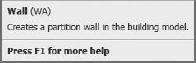
To increase your productivity even further, you may like to use keyboard shortcuts to speed up common commands and minimize interruptions to your workflow. When you hover your mouse pointer over any tool in the ribbon, the keyboard shortcut is indicated to the right of the tool name, as shown here.
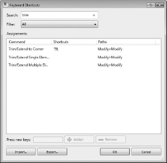
You can customize the keyboard shortcuts assigned to all commands in Revit. To access this tool, go to the View tab in the ribbon, find the Windows panel, and select User Interface ![]() Keyboard Shortcuts. When the Keyboard Shortcuts dialog box appears (Figure 3.24), you can search for commands in the Search box. Once you find a command to which you'd like to assign a shortcut, select it and type the shortcut in the Press New Keys box. Click the Assign button, and you will see the new shortcut added to the selected command. Click OK to close the dialog box, and the keyboard shortcuts will be ready for immediate use.
Keyboard Shortcuts. When the Keyboard Shortcuts dialog box appears (Figure 3.24), you can search for commands in the Search box. Once you find a command to which you'd like to assign a shortcut, select it and type the shortcut in the Press New Keys box. Click the Assign button, and you will see the new shortcut added to the selected command. Click OK to close the dialog box, and the keyboard shortcuts will be ready for immediate use.
FIGURE 3.24 Customize keyboard shortcuts for commonly used Revit commands.