
Modeling Site Context
In the previous sections of this chapter, you learned about the fundamental tools for editing and modifying model elements. Another set of tools you should become familiar with are the site tools. They allow you to create a context within which your building models can be situated. For example, a toposurface will create a hatched area when you view your building in a section, and it will function as a hosting surface for site components such as trees, shrubs, parking spaces, accessories, and vehicles (Figure 3.25).
FIGURE 3.25 A toposurface can host components such as trees, entourage, and vehicles.

The site tools in Revit are only intended to be used for the creation of basic elements, including topography, property lines, and building pads. Although editing utilities are available to manipulate the site elements, these tools are not meant to be used for civil engineering like the functionality found in AutoCAD Civil 3D.
In the following sections you'll learn about the different ways to create and modify a toposurface, how to generate property lines with tags, and how to model a building pad within a toposurface.
Using a Toposurface
As its name suggests, a toposurface is a surface-based representation of the topography context supporting a project. It is not modeled as a solid in Revit; however, a toposurface will appear as if it were solid in a 3D view with a section box enabled (Figure 3.26).
FIGURE 3.26 Toposurfaces will appear as a solid in a 3D view only if a section box is used.

You can create a toposurface in three different ways: by placing points at specific elevations, by using a linked CAD file with lines or points at varying elevations, or by using a points file generated by a civil engineering application. We'll examine these techniques in the following exercises.
CREATING A TOPOSURFACE BY PLACING POINTS
![]() The simplest way to create a toposurface is by placing points in your Revit project at specific elevations. To create a clean outer edge for your toposurface, we suggest drawing a large rectangle using detail lines in your site plan. When you are creating a toposurface by placing points, there are no line-based geometry tools; however, points can be snapped to the detail lines. The following exercise will show you how to create a toposurface by placing points:
The simplest way to create a toposurface is by placing points in your Revit project at specific elevations. To create a clean outer edge for your toposurface, we suggest drawing a large rectangle using detail lines in your site plan. When you are creating a toposurface by placing points, there are no line-based geometry tools; however, points can be snapped to the detail lines. The following exercise will show you how to create a toposurface by placing points:
- Begin by opening the file c03-Site-Tools.rvt, which can be downloaded from this book's companion web page at www.sybex.com/go/masteringrevit2012.
- Activate the floor plan named Site and you will see a rectangle created from detail lines.
- Go to the Massing & Site tab and from the Model Site panel, click Toposurface. Notice in the contextual tab in the ribbon that the default tool is Place Point.
- Notice the Elevation value in the Options Bar. Set the value of the points you are about to place.

Also note that the elevation values are always related to the Revit project base point. They do not relate to the elevation of any shared coordinates.
- With the Elevation value set to 0′-0″ [0 mm], place a point at each of the left corners of the rectangle.
- Change the Elevation value to 20′-0″ [6000 mm] and then place a point at each of the right corners of the rectangle. You will notice the contour lines of the surface begin to appear after the third point of the surface is placed.
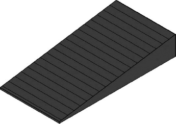
- In the contextual tab of the ribbon, click Finish Surface (green check) to complete the toposurface. Activate the default 3D view and you will see the sloping surface, as shown in Figure 3.27. And keep in mind that this will be a thin surface, not a solid. Notice that the 3D view in this project already has the Section Box property enabled. To adjust the section box, activate the Reveal Hidden Elements tool in the View Control bar.
FIGURE 3.27 A simple toposurface created by placing points
- Save the project file for use in subsequent exercises.
CREATING A TOPOSURFACE FROM IMPORTED DATA
![]() A common workflow you may encounter involves the use of CAD data generated by a civil engineer. In this case, the engineer must create a file with 3D data. Blocks, circles, or contour polylines must exist in the CAD file at the appropriate elevation to be used in the process of generating a toposurface in Revit.
A common workflow you may encounter involves the use of CAD data generated by a civil engineer. In this case, the engineer must create a file with 3D data. Blocks, circles, or contour polylines must exist in the CAD file at the appropriate elevation to be used in the process of generating a toposurface in Revit.
In the following exercise, you will download a sample DWG file with contour polylines. You must link the file into your Revit project before creating the toposurface.
- Create a new Revit project using the default.rte or DefaultMetric.rte template.
- Download the file c03-Site-Link.dwg from this book's web page.
- Activate the Site plan in the Project Browser.
- Go to the Insert tab in the ribbon and click the Link CAD button. Select the c03-Site-Link.dwg file and set the following options:
- Current View Only: Unchecked
- Import Units: Auto-Detect
- Positioning: Auto - Center To Center
- Place At: Level 1
- Click Open to close the dialog box and complete the insertion of the CAD link. Open a default 3D view to examine the results (Figure 3.28).
FIGURE 3.28 Linked CAD file as seen in a 3D view

- From the Massing & Site tab in the ribbon, click the Toposurface button. In the Tools panel of the Modify | Edit Surface ribbon, select Create From Import and then Select Import Instance.
- Pick the linked CAD file and the Add Points From Selected Layers dialog box will appear (Figure 3.29). Click the Check None button and then select the layers C-TOPO-MAJR and C-TOPO-MINR.
FIGURE 3.29 Select only the layers containing 3D contour information.

- Click OK to close the dialog box. It may take a few seconds to generate the points based on the contour polylines in the linked file, but they will appear as black squares when they have all been placed.
- If you would like to use fewer points to define the toposurface, click the Simplify Surface button in the contextual ribbon and enter a larger value such as 1′-0″ [250 mm].
- Click the Finish Surface button in the contextual ribbon to complete the toposurface. Change the visual style of the view to Consistent Colors to examine your results.
CREATING A TOPOSURFACE FROM A POINTS FILE
![]() A less common method for creating a toposurface, although equally effective when using linked CAD data, is using a points file. A points file is a text file that is usually generated from a civil engineering program. It must be a comma-delimited file (TXT or CSV format) in which the x, y, and z coordinates of the points are the first numeric values in the file. In the following exercise, we have provided a sample points file that was exported from AutoCAD Civil 3D using the XYZ_LIDAR Classification (comma-delimited) format setting.
A less common method for creating a toposurface, although equally effective when using linked CAD data, is using a points file. A points file is a text file that is usually generated from a civil engineering program. It must be a comma-delimited file (TXT or CSV format) in which the x, y, and z coordinates of the points are the first numeric values in the file. In the following exercise, we have provided a sample points file that was exported from AutoCAD Civil 3D using the XYZ_LIDAR Classification (comma-delimited) format setting.
- Open the file c03-Site-Points-Start.rvt, which can be downloaded from this book's web page.
- Download the file c03-Points.csv from this book's web page to your local computer.
- Activate the Site plan in the Project Browser.
- From the Massing & Site tab in the ribbon, click the Toposurface button. In the Tools panel of the Modify | Edit Surface ribbon, select Create From Import and then choose Specify Points File.
- Navigate to the c03-Points.csv file and click Open. Note that if you were using a TXT format file, you'd change the Files Of Type option to Comma Delimited Text.
- In the Format dialog box, select Decimal Feet. It is important to understand the units of the values in the points file to ensure the toposurface will be created at the correct scale. Click OK to close the dialog box.
- Click the Finish Surface button in the contextual ribbon to complete the toposurface. Open the default 3D view to examine your results. You may have to use the Zoom All command to see the extents of the new toposurface.
- Save the project file for use in subsequent exercises.
In the following sections, you can continue to use this file to explore the tools available for modifying a toposurface. Or you can download the completed version of the project, c03-Site-Points.rvt.
MODIFYING THE SURFACE WITH SUBREGION
The points file example in the previous exercise represents a section of terrain across Lake Mead, Nevada. If you wanted to define an area of the toposurface with a different material but not change the geometry of the overall surface, you would use the Subregion tool. In the following exercise, you will use this tool to create a region that will represent the water of the lake.
- Using the c03-Site-Points.rvt file, activate the Site plan from the Project Browser. In this view, there are dashed detail lines that represent the edge of the water.
- Go to the Massing & Site tab in the ribbon and click the Subregion tool.
- Switch to Pick Lines mode in the Draw panel of the contextual ribbon.
- Hover your mouse pointer over one of the dashed detail lines at the left side of the surface, Tab-select the chain of lines, and then click to select them. You will see a purple sketch line appear.
- Repeat step 4 for the dashed detail lines at the right side of the surface.
- Switch to Line mode in the Draw panel of the contextual ribbon and draw a line connecting each open end of the water edge lines, as shown in Figure 3.30.
FIGURE 3.30 The sketch boundary for a subregion must be a closed loop but can overlap the edge of the toposurface.

- Click Finish Surface in the contextual ribbon to complete the subregion.
- Activate the default 3D view and select the subregion you created in the previous steps.
- In the Properties palette, locate the Material parameter and click the ellipsis button to open the Materials dialog box. Locate and select the material named Site - Water. Note that you can easily find this material by typing Water in the search field at the top of the dialog box.
- Click OK to close the Materials dialog box; you will see the results in the 3D view, as shown in Figure 3.31.
FIGURE 3.31 The subregion is assigned a different material for visualization purposes.

When you use the Subregion tool, the geometry of the original surface remains unchanged. If you no longer need the subregion, you can select it and delete it. Be aware that topographic surfaces cannot display surface patterns assigned to materials.
USING THE SPLIT SURFACE TOOL
If you need to divide a topographic surface into separate parts for the purpose of editing the geometry, you can use the Split Surface tool. With this tool, you can sketch a single line along which the surface will be divided into two editable entities. These separate entities can be recombined later using the Merge Surfaces tool. In the following exercise, you will split a topographic surface and edit some of the points. Remember that you can also use Split Surface to delete a portion of a topographic surface.
- Open the file c03-Site-Tools.rvt you saved after the earlier lesson in this section.
- Activate the Site plan in the Project Browser.
- Go to the Massing & Site tab in the ribbon and click the Split Surface tool. Remember that you should use the Subregion tool if you only plan to assign a different material to the split region of the original surface.
- Select the topographic surface and you will enter Sketch mode. Using the Line mode in the Draw panel of the contextual ribbon, draw two lines that overlap the edges of the surface, as shown in Figure 3.32.
FIGURE 3.32 Sketch lines that overlap the edge of the topographic surface
- Click Finish Edit Mode in the ribbon and you will see the split surface highlighted in blue.
- Activate the default 3D view and turn off the Section Box option in the Properties palette.
- Select the split surface and click the Edit Surface tool in the Modify | Topography tab of the ribbon.
- Select the point at the outer corner of the topographic surface and change the elevation value in the Options bar from 20′-0″ [6000 mm] to 10′-0″ [3000 mm].
- Click Finish Surface in the contextual ribbon and you will see the result shown in Figure 3.33.
FIGURE 3.33 A split region after editing the elevation of a corner point
- To illustrate the difference between a split surface and other topographic surface edits, select the main surface and click Edit Surface in the contextual ribbon. Select the point at the upper corner opposite from the split region and change the elevation value to 10′-0″ [3000 mm]. Notice the difference in how the surface slope is interpolated between the other points on the surface (Figure 3.34).
FIGURE 3.34 Compare the difference between an edited split region (left) and an edited point directly on the surface (right).


Creating a Building Pad
A building pad in Revit is a unique model element that resembles a floor. It can have a thickness and compound structure, it is associated with a level, and it can be sloped using slope arrows while you're sketching its boundary. The building pad is different from a floor because it will automatically cut through a toposurface, defining the outline for your building's cellar or basement.
The process to create a building pad is virtually identical to that of creating a floor. Let's run through a quick exercise to create a building pad in a sample project:
- Open the file c03-Site-Pad.rvt, which can be downloaded from this book's web page.
- Activate the floor plan named Site in the Project Browser. You will see an existing topographic surface and property line. Notice that reference planes were created to demarcate the required zoning setbacks from the property line. Foundation walls have been created within these reference planes.
Note that you don't have to create a property line and walls before creating a building pad. You might create a building pad before any other building elements. Just realize that you can utilize the Pick Walls mode to associate the boundary of the building pad with the foundation walls.
- Activate the Cellar floor plan from the Project Browser.
- Go to the Massing & Site tab in the ribbon and click the Building Pad button. In the Properties palette, change the Height Offset From Level value to 0.
- Switch to Pick Walls mode in the Draw panel of the contextual ribbon and then pick the inside edges of the four foundation walls. You can use the Tab-select method to place all four lines at once.
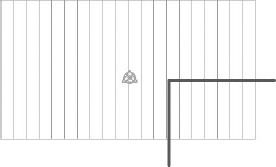
- Click the Finish Edit Mode button in the contextual ribbon to complete the sketch and then double-click the section head in the plan view to examine your results. Notice the top of the building pad is at the Cellar level and the poche of the topographic surface has been removed in the space of the cellar (Figure 3.35).
FIGURE 3.35 This section view illustrates how the building pad adjusts the extents of the topographic surface.

ADJUSTING THE SECTION POCHE FOR TOPOGRAPHIC SURFACES
If you would like to customize the settings for the fill pattern and depth of poche, locate the small arrow at the bottom of the Model Site panel in the Massing & Site tab of the ribbon. Clicking on it will open the Site Settings dialog box as shown here:
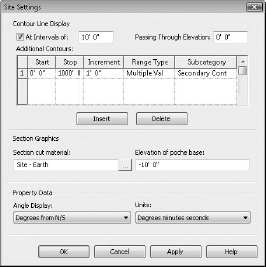
As you can see in this dialog box, you can change the Section Cut Material and the Elevation Of Poche Base settings. Note that the elevation value is in relation to the Revit project base point. You can also adjust the display format of contour lines shown on topographic surfaces as well as the units displayed by property lines.
Generating Property Lines
Property lines are used to delineate the boundary of the lot within which your building will be constructed. These special types of lines are different from simple model lines or detail lines because they can be tagged with standard property line labels that will display segment lengths along with bearings. The property line object can also report its area in a special tag.
You can create a property line in one of two ways: by sketching lines or by entering distances and bearings in a table. In the following exercise, you will create a simple property line by sketching, and then convert the sketched property line into a table of distances and bearings for comparison:
- Start a new project using either the Default.rte or MetricDefault.rte template file and activate the Site plan in the Project Browser.
- Go to the Massing & Site tab and click the Property Line button. When prompted by the Create Property Line dialog box, choose Create By Sketching.
- Switch to the Rectangle tool in the Draw panel of the contextual ribbon and draw a rectangle measuring 120′ × 70′ [36 m × 21 m].
- Click the Finish Edit Mode button in the contextual ribbon to complete the sketch.
- With the property line still selected, click the Edit Table button in the Modify | Property Lines tab of the ribbon. You will be prompted with a warning that you cannot return to Sketch mode once the property line has been converted to a table of distances and bearings. Click Yes to continue.
- You will now see each vertex of the property line expressed as a distance and a NE bearing, as shown in Figure 3.36.
FIGURE 3.36 A property line can be defined in a table of distances and bearings.

TAGGING PROPERTY LINES WITH AREA
In standard construction documentation, it is customary to annotate each vertex of a property line with its distance and bearing. There are two different types of tags you can use to annotate property lines. In the following exercise you will load these two types from Revit's default library and tag each segment of the property line as well as display the area contained within it.
- Go to the Insert tab of the ribbon and click the Load Family button. Navigate to Revit's default library; double-click the Annotations folder and then the Civil folder.
- Locate the following files and select them both by pressing the Ctrl key (the equivalent Metric library families are shown in parentheses):
- Property Line Tag.rfa (M_Property Line Tag.rfa)
- Property Tag - SF.rfa (M_Property Tag.rfa)
- Click Open to load both families.
- Go to the Annotate tab of the ribbon and click Tag By Category and uncheck the Leader option in the Options Bar.
- Click on each segment of the property line to place the tags indicating the distance and bearing, as shown in Figure 3.37.
FIGURE 3.37 Tags are applied to display the distance and bearing of each segment of the property line.

Now that you have tagged the individual vertices of the property line, it is time to display the area within the property line. This process is not the same as applying an area tag because an area object doesn't exist for the property line. Instead, the annotation family Property Tag - SF.rfa (M_Property Tag.rfa) is designed to be applied to the property lines when all its segments are selected.
You can try this with the property line you created earlier. Go back to the Annotate tab in the ribbon and click Tag By Category. Instead of picking a single vertex of the property line, hover your mouse pointer over one segment and use Tab-select to highlight the entire chain of property line segments. Click to place the property area tag. Click the question mark above the area to change the name of the property line, as shown in Figure 3.38.
FIGURE 3.38 Use Tab-select to place a property area tag for all segments.

Cut and Fill Schedules
As we mentioned earlier in this section, Revit's site tools are not meant to replace civil engineering software programs. We have shown you how to create a topographical surface in a variety of ways as well as some methods of modifying these objects. There is also a way to quickly quantify how much earth is displaced by proposed changes to existing topography. This is commonly referred to as a cut/fill schedule.
One easy way to demonstrate the use of a cut/fill schedule is through the creation of a building pad that automatically modifies the topographic surface. Let's go through a quick exercise to examine this process:
- Open the file c03-Site-Cut-Fill.rvt, which can be downloaded from this book's web page.
In this file, notice that the topographic surface has been assigned to the Existing phase.
- From the View tab in the ribbon, click Schedules and then select Schedules/Quantities to open the Edit Schedule dialog box.
- From the Category list, choose Topography and then click OK.
- In the Fields tab of the Schedule Properties dialog box, choose Name, Projected Area, and Net Cut/Fill, clicking Add after each one.
- Activate the Cellar plan from the Project Browser and create a building pad in the same way you created one earlier in this section.
After you complete the creation of the building pad and the topographic surface is modified, notice that the Net Cut/Fill values in the topography schedule still have a value of 0. This is because the Graded Region tool must be used on a surface to generate the differences required to calculate what volume must be cut versus filled in the proposed design.
- Tile the open Revit windows so you can see both the default 3D view and the topography schedule.
- From the Massing & Site tab, click the Graded Region tool and then select the topographic surface. When the Edit Graded Region dialog box appears, choose the option Create A New Toposurface Exactly Like The Existing One. This effectively creates overlapping existing and proposed surfaces, which will allow Revit to schedule the differences between the two.
- When you select the surface, you will see the volume values in the topography schedule update to reflect how the excavation for the building pad affected the overall soil. Note that this type of calculation does not account for various construction methods such as backfilling.
Try selecting the building pad and changing the Height Offset From Level value. Observe how the Net Cut/Fill values change as the pad helps define the scope of excavation on the site.
You can also make the topography schedule easier to read by assigning descriptive information to each topographic surface. Select the surface and enter a value in the Name field in the Properties palette. Change the name of the main surface to Existing Grade and then locate the surface where the building pad is. Change its name to Pad Area and observe the topography schedule once again.