
Adding Dimensions
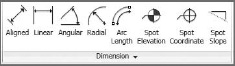
![]() Dimensions are used to convey the distance or angle between elements or parts of elements. In Revit, a dimension is a bidirectional annotation that essentially tags distance or size. This means that you can edit the distance directly within the dimension string to move elements to a specific distance apart; likewise, the dimension updates automatically as the distance between elements changes. Dimensions are annotations, making them view-specific elements that appear only in the view where they're drawn. The Dimension tools are located on the Annotate tab.
Dimensions are used to convey the distance or angle between elements or parts of elements. In Revit, a dimension is a bidirectional annotation that essentially tags distance or size. This means that you can edit the distance directly within the dimension string to move elements to a specific distance apart; likewise, the dimension updates automatically as the distance between elements changes. Dimensions are annotations, making them view-specific elements that appear only in the view where they're drawn. The Dimension tools are located on the Annotate tab.
Like all annotations in Revit, dimensions adjust to the scale of the drawing. They will always appear at the proper scale in the view. If you change the view scale, the dimensions automatically resize.
By default, a linear string of dimensions only dimensions parallel entities. Nonparallel elements by their very nature have a dynamic dimensional relationship. Dimensions in Revit always read from the bottom or from the right following the standard architectural sheet layout conventions. To place a dimension, choose any Dimension tool and begin selecting entities in a sequence. You can keep selecting multiple entities in a given direction, creating a dimension string across your drawing.

![]() Once the dimensions are placed, you can relocate them at any point either as an individual dimension or for an entire string. Select the dimension and grab the blue square grip. By selecting and holding on this element, you can move the witness line to a new host element without having to re-create the entire dimension string.
Once the dimensions are placed, you can relocate them at any point either as an individual dimension or for an entire string. Select the dimension and grab the blue square grip. By selecting and holding on this element, you can move the witness line to a new host element without having to re-create the entire dimension string.
For continuous and equal dimensions, you can override the EQ value. Select the EQ text value and a Dimension Text dialog box opens (Figure 9.45). Now you can replace individual portions of text with custom values (but not numeric values).
FIGURE 19.45 Changing the EQ value on an instance basis

If you want to customize the EQ field as part of your project template, this is easily done as well. Go to the Type Properties dialog box for the type of text and change the value from the default EQ to your custom value, which then changes for this text type throughout your entire project (see Figure 19.46).
FIGURE 19.46 Changing the EQ value on a type basis

To customize your dimension leaders, select the type properties for the dimension style that you want to customize. There are five parameters that can customize your dimension leaders (Figure 19.47):
- Leader Type
- Shoulder Length
- Leader Tick Mark
- Show Leader When Text Is Moved
- Text Location
FIGURE 19.47 Changing the leader value on a type basis

And finally, you can customize the visibility of individual text element in dimensions by selecting the value in the dimension and changing the Segment Dimension Leader Visibility setting (Figure 19.48).
FIGURE 19.48 Changing the leader visibility
