
Intuitive Massing
Since this is an intuitive mass form, we'll cover how to create a surface and then assign host elements to the surface. This is a great way to create complex walls and roofs. Then we'll explain how to assign patterns to the surface. Start by opening a new project, and create a third level, as shown in Figure 9.44. You'll use these levels as controls for the Spline Through Points that will generate our first surface.
FIGURE 9.44 Creating an additional level

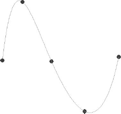
Select In-Place Mass and go to a top 3D view. Then create a Spline Through Points as shown on level 1 (Figure 9.45). Although this might seem like a simple shape, the resulting form will be quite complex—just be patient!
FIGURE 9.45 Spline Through Points
In-Place Surface
Now create another Spline Through Points using Level 3 as a reference, as shown in Figure 9.46. Since you're working in a 3D view, you'll be able to see both splines at the same time.
Now rotate the view so that you can see both splines separately. Select them both and then select Create Form, as shown in Figure 9.47.
Figure 9.48 shows the resulting surface.
FIGURE 9.46 Second Spline Through Points

FIGURE 9.47 Selecting Create Form


WALL BY FACE
![]() Once you've selected Finish Mass, you'll be able to create a wall by face and assign it to this form. Go to the Home tab and select Wall By Face, as shown in Figure 9.49.
Once you've selected Finish Mass, you'll be able to create a wall by face and assign it to this form. Go to the Home tab and select Wall By Face, as shown in Figure 9.49.
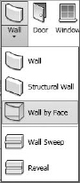
Figure 9.50 shows the resulting wall. The mass surface has been turned off in order to show only the wall.

Now let's return to the in-place mass and change the references. To do this, you select the mass and then click the Edit In-Place button. But before starting, you may want to hide the wall so that only the mass and its references are shown.
By selecting each of the controls, you'll notice you can move them in X-, Y-, and Z-directions. Adjust the controls as shown in Figure 9.51.
Now finish the mass and unhide your wall in the view. Select the wall and then choose the Update To Face option (Figure 9.52).
The wall will update to conform itself to the modified face, as shown in Figure 9.53.
Now hide the wall, select the mass surface, and return to editing in place. Add another Spline Through Points using Level 2 as a reference, as shown in Figure 9.54.

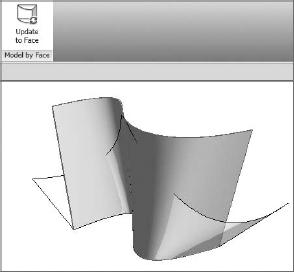

FIGURE 9.54 Adding another Spline Through Points

Select the surface and you have the option to dissolve the surface (Figure 9.55). Go ahead and do this. Then select all three splines and re-create the surface.
FIGURE 9.55 Dissolving the surface

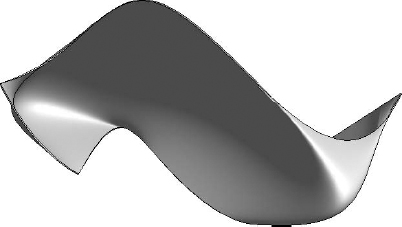
Once the surface has been revised, finish the mass and update the wall as done previously. Your updated wall will not look exactly like Figure 9.56. What's important is that you grasp the principles and the process. If the changes you made were so complex that the wall can't be updated to match the new face, just delete it and re-create it.
FIGURE 9.56 Finishing the family and updating the wall
PATTERN-BASED SYSTEM
Three steps are involved in assigning a pattern to a mass surface. First you divide the surface, then you assign a pattern to the surface, and finally you assign a component to the pattern.
- Rather than start from scratch, create a copy of the surface previously created. Now select the mass surface and enter Edit In-Place mode. Select the surface. Be sure to delete the wall from the copied mass since you'll only need the surface.
- While in Edit In-Place mode, select the surface and choose Divide Surface from the contextual divide palette (Figure 9.57).
FIGURE 9.57 Divide Surface tool
The default divided surface will look like Figure 9.58.
- Once the surface has been divided, you can assign a pattern to the surface. The pattern will not contain any geometry; it's a lightweight method of resolving the eventual surface that will be replaced with more resolved geometry.
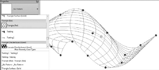
- Select the surface and you'll see that no pattern has been applied, as shown in Figure 9.59. Experiment with assigning different patterns from the Properties drop-down list.
- Select the Triangle (Flat) pattern (Figure 9.60).
FIGURE 9.60 Selecting the Triangle (Flat) surface pattern
- The resulting surface will be faceted with an analytic triangular pattern (Figure 9.61).
FIGURE 9.61 The result of choosing the Triangle (Flat) pattern

- Take a moment to investigate the edge conditions of your analytic surface. There are three options: Partial, Empty, and Overhanging. Select the surface and enter Edit In-Place mode to investigate these three options.
The Partial option allows the triangulated surface to align with the edge of the mass surface (Figure 9.62).

The Empty option doesn't allow the partial panel to be created (Figure 9.63).

The Overhanging option completes the partial panels to extend beyond the mass surface (Figure 9.64).
FIGURE 9.64 Overhanging option

- Select the Overhanging option. Now exit Edit In-Place mode.

PATTERN-BASED PANEL
Now you're going to create a pattern-based panel. Start a new family component and open the Curtain Panel Pattern Based template (Figure 9.65).
FIGURE 9.65 Curtain Panel Pattern Based template

Then follow these steps:
- To keep things simple, every pattern-based family that you'll need to create is in this family template. Just select the grid that contains the reference lines and you'll be able to select from all the panel options in the Properties tab (Figure 9.66).
FIGURE 9.66 Panel options in the Properties tab

- Select a few different options from the drop-down menu and you'll notice that the patterns change accordingly. Eventually you'll want to select the Triangle (Flat) type, as shown in Figure 9.67.
FIGURE 9.67 Triangle (Flat) template

- Apply the template and then update the panel in your project by reloading it into your project. This process is important, because if something breaks you'll know which step to reconsider.
- Select the reference planes and then select Create Form. Again, only create the surface, not the geometry (Figure 9.68). Save the family (we've called it Testing.rfa) and then load it into your massing project.
FIGURE 9.68 Creating only the surface form
- To assign the panel that you just created to the massing form, you need to select the mass and enter Edit In-Place mode. Once you've done this, select the mass again and open the Properties drop-down menu for your mass surface. Notice that in addition to the options for assigning a pattern, you can now assign geometry (Figure 9.69).
- Assign this component to the mass. Then exit Edit In-Place mode. Now hide the mass so that only your panel will display (Figure 9.70).
- Return to the panel family. It's about to get very interesting!
Select all three reference points and copy above the work surface, as shown in Figure 9.71. You can use graphic display options to turn off the gradient background.
FIGURE 9.69 Options for assigning geometry

FIGURE 9.70 Panel assigned to mass surface
FIGURE 9.71 Copying the three reference points

- Go to a top view and move the points similar to Figure 9.72.
FIGURE 9.72 Moving the reference points

- Join the reference points with new reference lines, as shown in Figure 9.73.
FIGURE 9.73 Joining the reference points with new reference lines

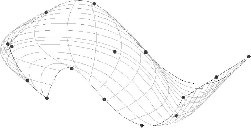
- Select all the reference lines and create a new form. This will result in a blended form, as shown in Figure 9.74.
- Reload the family into the project. Your components will update, creating a surprisingly complex form (Figure 9.75).
FIGURE 9.75 The updated components, resulting in a complex form


By revisiting the family and updating in the project, you can create interesting and complex forms. In Figure 9.76, the panels were created by associating a simple extrusion with a series of reference lines that were offset from the original sketch.
FIGURE 9.76 Voided blended panels

Figure 9.77 shows the resulting family, which has been assigned to a newly created blended surface. If you want to further investigate this project, download the c09_Intuitive_Massing_Surface.rvt file in the Chapter 9 folder.

Of course, creating complex form-driven systems isn't for everyone or every project. But we think that CNC and other forms of rapid prototyping are going to make mass customization increasingly approachable over the next few years.
If you are interested in generative form making, head over to Zachary Kron's blog. He works for Revit factory as a software analyst. His blog is at http://buildz.blogspot.com/ and his YouTube channel is www.youtube.com/user/zachkron. He's a great source of geometry, rule-based customization, and in some cases, API-driven customization.
In-Place Solids
Creating in-place mass solids is quite easy once you understand the process of creating and modifying the various forms in Revit. Let's start by entering in-place massing mode and selecting a rectilinear shape created from model lines (Figure 9.78). You should also select the option to make a surface from the closed loops that are being created. The other option would be to not make a closed loop, but you're creating a simple extrusion (initially), so this will save a step.

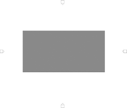
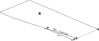
- Sketch a form similar to the one shown in Figure 9.79. Specific dimensions are not important; it's more about the proportions.
FIGURE 9.79 Plan view of sketch
- Open the default 3D view and select the face of the surface that you just created. When you select this surface, controls become available that allow you to pull the surface into a solid (Figure 9.80).
FIGURE 9.80 Creating a solid form

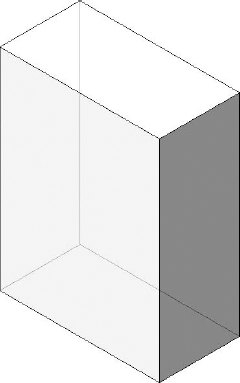
- Pull the surface up until it resembles the form shown in Figure 9.81. Again, it's more about proportion than dimensions.
There are a number of shape handles that allow you to modify each face, edge, and intersection. Simply hovering over each face, edge, and vertex will highlight the appropriate control. You may also find it useful to tab through to select the desired control.
If you select a face, you'll be given the control shown in Figure 9.82.

Selecting an edge will give you the ability to modify the edge of a form (Figure 9.83).
Selecting the intersection allows you to modify the location of a vertex (Figure 9.84).
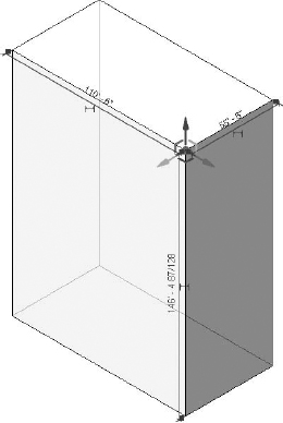
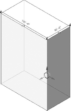
The control arrow allows you to modify the selected element parallel in the direction of the arrow, while the angled indicators of the same colors as their corresponding arrow will allow you to modify the location of the selected element perpendicular to the arrow (Figure 9.85).
FIGURE 9.85 Parallel and perpendicular control

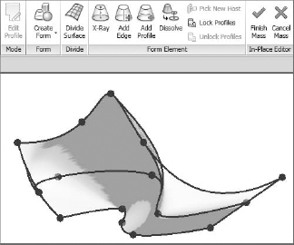
First, let's turn on X-ray mode so we can see any of the profiles and controls (Figure 9.86). X-ray mode is helpful for seeing all the controls that are available as well as the trajectory control of the extrusion.
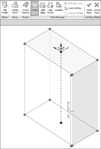
Now that X-ray mode has been enabled, let's look at the options that Revit provides for turning a rather simple, extruded form into something complex. An edge (Figure 9.87) may be added to an existing form that is from vertex to vertex or parallel with the trajectory of the form (shown as a dotted line from the upper to the lower face).
Once the edge has been added, you may push or pull the face adjacent to the new edge, as shown in Figure 9.88.
You may also push or pull the edge that has just been created, which will stretch both adjacent faces (Figure 9.89).


Pushing or pulling the edge that is perpendicular to the edge previously created will create curved and warped surfaces (Figure 9.90). This is fine, since the form that you're creating can be rationalized later when adding a pattern to the surface.

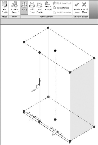
But if you'd rather rationalize the form now (and in doing so remove any warped surfaces), then add another edge from vertex to vertex, as shown in Figure 9.91. Doing so will force the faces to become triangulated and planar, as three points define a plane.

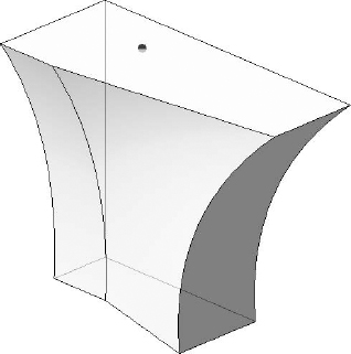
Pulling the top edge away from the vertical plane of the form results in a more dramatic form, as shown in Figure 9.92. Again, it's not necessary to maintain the exact dimensions; it's about trying to keep the proportions appropriate. This is what intuitive form making is all about!
FIGURE 9.92 Pulling the upper edge

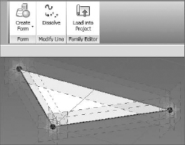
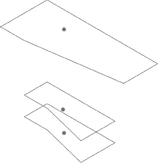
Using the Dissolve function (Figure 9.93) will remove the mass solid and leave behind the analytic profiles that define the solid. The dot in the center of each plane is a control that will allow you to edit the elevation, rotation, and location of the shape.
FIGURE 9.93 Using Dissolve to remove the mass solid
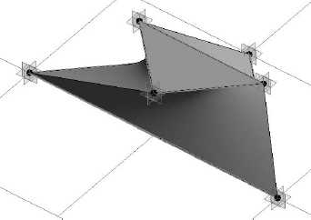
Selecting the profiles together and then choosing the Create Form command will stitch the form back together in a way that interpolates the shape as more of a lofted blend (Figure 9.94). You could also add more profiles to the shape.
FIGURE 9.94 Making a lofted blend from three profiles
However, if you select only two profiles at a time, then the following occurs (Figure 9.95). This form was created by first selecting the bottom and middle profiles and then creating the form. Then the middle and upper profiles were selected and another form was created. The result is straight—rather than curved—interpolation between the profiles.
FIGURE 9.95 Making a blend from two profiles

Rather than select either of the two previous options, let's alter the front edge of all three profiles. Start by deleting the existing edge (you'll have to tab to select just this edge and then delete), as shown in Figure 9.96.
Now you'll want to draw a fillet arch to rejoin the two remaining edges. To do so, you'll have to set the work plane of the shape as shown in Figure 9.97. Just tab through until the horizontal work plane is highlighted and then select it.
FIGURE 9.97 Selecting the work plane

Once the work plane is selected, you'll be able to draw additional model lines. In this example, you're using a fillet arch to connect the lines (Figure 9.98). You'll do the same thing for the other two shapes.
FIGURE 9.98 Completing the profile

Now select the lower two profiles and choose Create Form. Then do the same with the upper two profiles. Finally, you'll want to remove any blends by adding an edge to the opposing edges.
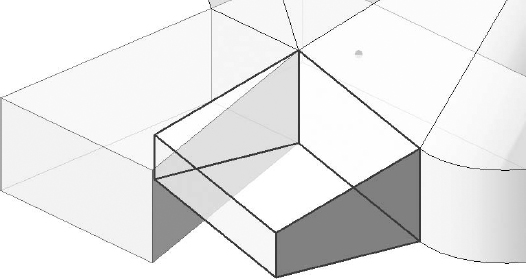
Creating additional mass solids is easy. You can select an existing face and then select the Create Form command, as shown in Figure 9.99.

The same Create Form command was used to create the form shown in Figure 9.100.
FIGURE 9.100 Creating another form

In Figure 9.101, we've extended both faces considerably from their initial depth after using the Create Form option. Notice the locked relationship, which will only allow the faces of the form, not the edges or vertices, to be manipulated. In other words, you wouldn't be able to push or pull the top of the form up. You can remove this restriction by clicking the lock icon.
FIGURE 9.101 Unlocking a reference

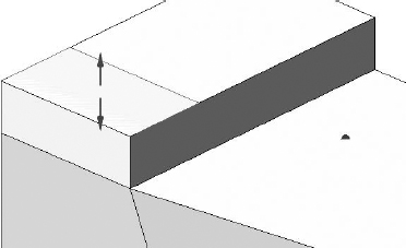
Once unlocked, the edge of the face is easily moved down to give a slope to the edge at the front of the form (Figure 9.102).
FIGURE 9.102 Modifying the edge
There will be many cases when creating existing geometry from an existing face will give you more mass than you need in your model. In these cases, it's simply a matter of drawing more model lines on the surface of the existing form. Then you'll be able to quickly and easily push and pull the faces, edges, and vertices of the resulting form (Figure 9.103).

The in-place solid mass is finished, and the masses from Figure 9.102 have been joined so that the edge between the two masses is now visible (Figure 9.104). Go ahead and finish the in-place solid mass and return to the regular project environment.
Once you're out of In-Place Massing mode, you'll notice that if you select the model, many shape handles simultaneously appear in the form of solid blue arrowheads (Figure 9.105). You can use shape handles to push and pull your solid mass, but you won't be able to modify edges or vertices without reentering In-Place Massing mode.
Figure 9.106 shows the finished mass in a perspective view. Both solids and voids can be used to complete a mass form. Whereas solids will add more geometry, voids will remove geometry from your mass.

FIGURE 9.105 Using shape handles


To demonstrate this, we'll return to In-Place Massing mode and create another face on the top of the existing form (Figure 9.107).
STARTING VOIDS AS SOLIDS
If you create the void as a void, it will immediately cut the solid mass and become invisible. This can be really annoying when you're trying to resolve your design and want to selectively cut after you've intuitively resolved a design idea. Fortunately, there's a better way, as described in the following exercise.
Follow these steps:
- Rather than create a void, start by creating a solid, even a solid of a different color and category (if necessary) to keep things clear during your design iteration.
- Select the solid mass and convert it to a void, as shown in Figure 9.108.
FIGURE 9.108 Converting a solid to a void

Figure 9.109 shows the result of the void cutting the solid. Keep in mind that if you want to convert the void back to a solid, you'll have to un-cut any geometry that was being cut by the void. But the nice thing about this technique (converting solids to voids and then cutting) is that you've selectively cut only the solids that you wanted to cut. Had you modeled the void as a void, you would have found that the void was cutting many solids and you'd have to un-cut solids that weren't even overlapping with the void!

Overall, creating solid masses intuitively is a great way to establish, analyze, and visualize your overall design idea. As you saw earlier in the chapter, mass floors allow you to even quantify gross floor areas before you've committed to geometry.
Furthermore, it's possible to put different intuitive massing ideas inside different design options (covered in Chapter 11), so that many ideas can live in a single Revit project file. Simply initiate worksharing and create worksets for each study mass. Multiple team members will be able to see one another's work at the same time and in context with their design ideas. This is the holistic kind of team approach to design information that makes massing in Revit a unique and valuable design tool. If you'd like to investigate this file further, you can download the file c09_Intuitive_Massing_Solid.rvt from the Chapter 9 folder.
Next we'll investigate parametric and formulaic solid mass creation in the Family Editor.