
Massing UI and Functionality
You might not think that you need to use massing tools when you first begin using Revit if you tend to design conventional or rectilinear buildings. But you'll quickly find that just because you don't create complex buildings, a lot of buildings contain complex features or parts that require a firm understanding of the massing tool.
Massing is certainly used to create masses—that is, forms with geometric substance (solids and voids). But the massing tool is also used to create complex surfaces that can be used to create relationships to other host elements. Without these mass- or surface-based relationships, it'd be really hard to create and reiterate system families such as walls and curtain walls. You'd essentially have to start over when the design changed. Massing allows you to create a lightweight design idea, evaluate it, and then associate some real-world building elements with the massing element. To change the real-world building element, you change the lightweight design idea first.
Another important thing to know about massing is that masses can be created in both the project environment as well as the Family Editor. There's a lot of overlap of functionality in each case, but there's also a lot of important functionality missing. So, what's the difference?
The main difference as to whether you create massing in-place or in the Family Editor doesn't depend on the kind of shape or surface you want to create. Solid and surface forms can be created in both the project and Family Editor environments. Rather, it depends on how you want to create the massing and how you want to change the mass once it's been created.
Intuitive and Formula Mass Creation
Generally speaking, there are two ways to create form. The first approach tends to create masses more intuitively; the second approach tends to create masses more formulaically. Intuitively created masses could probably be created right in the project environment as an in-place mass, but if the shape that you're trying to create needs to be driven by formulas, you're probably better off opening the Family Editor and creating the shape there.
When using the intuitive method, you can model just about anything in the project environment, both host and component families. We strongly recommend that you don't model component families in-place unless the condition is quite unique and exceptional, because the moment you need to create another just like it, you will have created a copy. If you have to change both of them, you'll have to change them both manually. It's best to model component families in the Family Editor.
But once in a while you'll have to create a complex host element that can't be created with the standard tools, and you'll have to use the formulaic method. As you've noticed by now, there are no templates in the Family Editor for host (or system) families such as walls, roofs, and floors. If you need to create these, they'll have to be created in the project environment. You can do so in one of two ways: create a mass or surface (using massing) or simply model it in place. If the structure of the wall varies significantly, you'll probably just want to model the wall in place. But if the structure is more consistent, it'll be easier to create a mass or surface form, and then associate the wall with this form.
In-Place Masses
![]() Figure 9.1 illustrates the intuitive method. It was created all the way back in 2001 when a lot of people thought Revit couldn't be used to create complex shapes. This was kind of true for a while, but once blends were introduced, these kinds of complex shapes were immediately possible.
Figure 9.1 illustrates the intuitive method. It was created all the way back in 2001 when a lot of people thought Revit couldn't be used to create complex shapes. This was kind of true for a while, but once blends were introduced, these kinds of complex shapes were immediately possible.
This wall wasn't created by starting with a mass; it was created by creating the blend in-place in the Wall category. Notice how the top and base of the wall are not consistently thick. It's narrower in some places and wider in others as it moves from bottom to top.
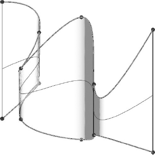
But if the wall was meant to be consistently wide, it would be more appropriate to make the mass or surface first, and then assign the wall to the form (Figure 9.2). Notice how the top and bottom of the wall are the same width overall.
FIGURE 9.1 Complex in-place wall
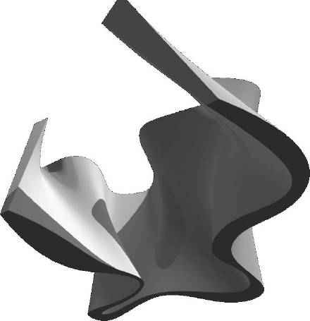
FIGURE 9.2 Wall created from in-place mass surface

At the end of the day, the previous two figures were created in the project environment through intuitive decision making. There were no formulas or parameters or rules; we just created the shape directly—in the moment, so to speak.
Family Component Masses
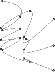
The other way to create a form is to first start to think about the rules that you want to create (and later reiterate) for the form you're trying to accomplish. Figure 9.3 illustrates this kind of form.
FIGURE 9.3 Massing created in the Family Editor

The rules that were created resulted in a form that would programmatically rotate and narrow depending on its relative elevation. Later, geometry was assigned to this form along the edges. Creating this kind of form as an in-place object would be tedious, and modifying it would be extremely time-consuming.
Now we'll talk about creating massing as both in-place and in the Family Editor.
Floor Area Faces and Scheduling Masses
Whether you create masses in-place or in the Family Editor, you're able to generate floor faces (not the actual floors) and schedule important metadata before you've even begun to assign actual geometry to the masses. This is important to do because the masses will be light in your project. You should use them to establish your design idea before committing a lot of complex geometry.
In-place mass forms can be both solid- and surface-based forms. You can start them two ways. The first way is to select Component ![]() Model In-place from the Home tab (Figure 9.4).
Model In-place from the Home tab (Figure 9.4).
FIGURE 9.4 Selecting Model In-Place

When you select this option, the dialog box in Figure 9.5 appears. Be sure to select the Mass category.
FIGURE 9.5 Selecting the Mass category

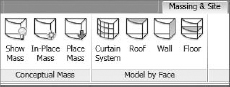
The other way is to select the Massing & Site tab, as shown in Figure 9.6. From the Conceptual Mass panel, select In-Place Mass. In either case, when you start to create the mass, you'll want to have the Mass category visible (it's turned off by default in all views).
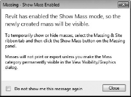
Rather than confuse you by allowing you to create objects that wouldn't be visible, Revit prompts you to turn the category on (Figure 9.7). This warning only appears when you're using the Massing & Site tab.
FIGURE 9.7 Revit enables the Show Mass mode.
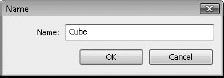
Once you close this dialog box, you'll be given the opportunity to name your in-place mass. In this case you're going to name the mass Cube (Figure 9.8).
SIMPLE MASS CREATION
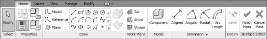
After you've named the mass from the previous steps and clicked OK, you'll be shown the contextually specific Massing toolset. The Home tab contains the tools that you'll use to create solid and void geometry as well as surface-generated masses, as shown in Figure 9.9.
FIGURE 9.9 Massing functionality
When you're finished creating your mass, you'll have to select Finish Mass (or Cancel Mass) in order to return to the regular project environment.
In Figure 9.10, we've created three masses: Cube, Pyramid, and Sphere.
All three of these shapes have been created as completely different masses, not within the same in-place session. As each form was finished, the mass was completed and the process was repeated for each mass. The difference is that in your Family Browser, each mass will show up as a separate line item (Figure 9.11).
Starting with the cube, its dimensions are 100′ × 100′ × 100′ (about 30 m × 30 m × 30 m). The base of the pyramid is the same size as the cube with equal sides tapering to the same height. And the sphere is the same width as the cube.
FIGURE 9.10 Cube, Pyramid, and Sphere
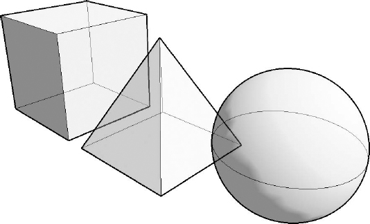
FIGURE 9.11 Separate masses in the Family Browser

FLOOR AREA FACES
![]() Once each shape is complete, it's important to understand how to create floor area faces. Keep in mind that the process would be the same for in-place masses as for those created in the Family Editor.
Once each shape is complete, it's important to understand how to create floor area faces. Keep in mind that the process would be the same for in-place masses as for those created in the Family Editor.
To create floor area faces, follow these steps:
- Create more levels above the two default levels. Do this as shown in Figure 9.12. This will give you a total of 10 levels.
FIGURE 9.12 Intersecting levels

- Now select all the masses and click the Mass Floors button in the contextual Model panel (Figure 9.13).
FIGURE 9.13 Mass Floors command

- Select all the levels, as shown in Figure 9.14.
FIGURE 9.14 Selecting all levels

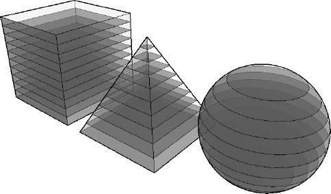
The solid masses will be intersected by floor faces, as shown in Figure 9.15. Now the masses and floor faces can be calculated and scheduled.
SCHEDULING MASSES
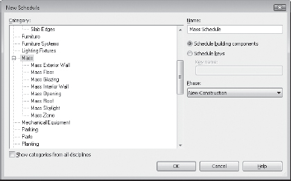
Select Schedules from the View tab, and you'll be given the option to schedule both Mass and Mass Floor (Figure 9.16). In this case we'll schedule the masses so we can do a comparative analysis between the different mass types.
FIGURE 9.16 Creating a schedule
Select the categories as shown in Figure 9.17 and add them to the scheduled fields.

For this example, we'll also show you how to create two calculated values. This will allow you to calculate the overall volume compared to the floor area, as well as the overall surface area compared to the floor area. Schedules like this will be helpful during the early design process to help you understand how efficient the space of your design is compared to the volume and surface area required to contain that space.
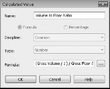
- Select the Calculated Value button in the Fields tab of the schedule properties to create the volume-to-floor ratio. Note the formula as shown in Figure 9.18. To keep the units consistent, you divide the gross volume by 1′ before dividing by the gross floor area.
FIGURE 9.18 Volume-to-floor ratio
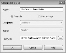
- Create the calculated value to compare the surface-to-floor ratio, as shown in Figure 9.19.
FIGURE 9.19 Surface-to-floor ratio
- Finish both calculated values and finish the schedule. You'll see the Mass Schedule as shown in Figure 9.20. Notice that proportionally, a sphere and a cube have efficient floor areas compared to their required surface area and volume.
FIGURE 9.20 Completed schedule

On the other hand, the pyramid mass will require significantly more surface and volume to create the same relative surface area as a cube or a sphere; as a result, it takes far more surface area than a cube to contain the same space. Perhaps this is why pyramids aren't a common building mass—it's too expensive. Pyramids only pay for themselves if the labor is cheap or the owner has a lot of money to spend.
If you want to download this file, it's in the Chapter 9 folder and is named c09_Mass_Schedules.rvt.
CREATING MASSES
How you create masses (surface or form) differs significantly from the UI used to create other standard content in Revit. When you're creating standard project content, you tend to think of the form that you're creating and then start to create that form in a discrete mode that isolates you from doing anything else until the form making is complete (Figure 9.21). In some ways, this is a Noun > Verb approach: You know the form that you want to create and then you create it.
FIGURE 9.21 Nonmassing form creation
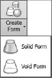
Creating massing in Revit still requires that you know the form that you intend to create, but you're not required to select a particular Noun-type to get started. Rather, you simply start by creating the sketch-based elements that would define your shape. Then you select them as a group and choose the Create Form option (Figure 9.22). This will allow you to create both solids and voids.
FIGURE 9.22 Create Form option
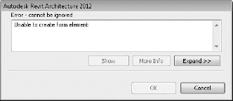
In the event that you don't select enough information for the Create Form command to make sense, you'll get the warning shown in Figure 9.23.
FIGURE 9.23 Create Form warning
Both solid and surface may be created from model lines or reference lines (Figure 9.24). But the differences are important. Keep in mind that your ability to further iterate the form that you create depends on whether you use model or reference lines to generate the form, even though the forms created may at first look exactly the same.
FIGURE 9.24 Draw panel for both model and reference lines

If your intent is to simply create a form that is not likely to require further iteration or rule-based parameterization, using model lines is fine. But if you intend to parameterize the form with formulas and other rules, it's best to start with reference lines. Figure 9.25 shows the subtle graphic difference between the two line types. The model line is on the left, and the green reference line is on the right.
FIGURE 9.25 Model lines and reference lines

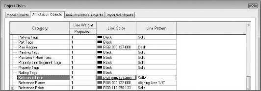
Since the difference is so subtle on the screen, we recommend that you give your reference lines more thickness and lighten the default green color so that they stand out better. You can do so using the Object Styles settings (Figure 9.26).
FIGURE 9.26 Object styles for reference lines
Because reference lines allow for more flexibility, we recommend that you use reference lines (even when you don't think you need to). Another reason is because you can create faces from closed loops if you use reference lines (Figure 9.27). This option isn't available when you select model lines. Selecting a closed loop of model lines will only create a form (solid or void), never a face.
FIGURE 9.27 Option to create face or solid from reference lines

MASSING SURFACES
All of the shapes that you'll create in this chapter are going to be done using reference objects.
Figure 9.28 shows a number of linetypes: Spline Through Points, Spline, Curve, and Line.
FIGURE 9.28 Reference line segment types

As you can see in Figure 9.29, each of these reference lines have different control points that allow for further control.
FIGURE 9.29 Reference line control points
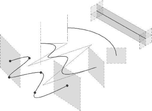
Since these are not closed loops, the form that will generate from each of these segments will only be face or surface (Figure 9.30). You generate the form by selecting each of the lines (one at a time, not together) and then selecting Create Form.

You can also create surface-based forms from more than one line at a time. The result is a surface that can be controlled in more complex ways than a single line.
For example, we'll take the Spline Through Points. The form on the left creates a face that is controlled by a single reference line, whereas the form on the right is a face controlled by two (and it could be more) reference lines (Figure 9.31).
FIGURE 9.31 Surfaces based on multiple splines
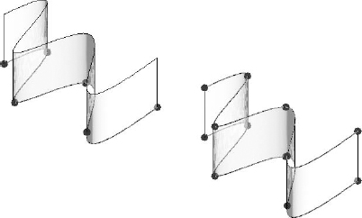
Moving the location of the control points on the form on the left maintains a consistent height to the top of the surface previously generated, whereas moving the control points of the surface on the right will create a surface that varies in height (Figure 9.32).
FIGURE 9.32 Single and multispline surfaces

After a surface is generated, it's also possible to add more profiles, as illustrated by Figure 9.33.
After the profile was added, the location of the profile was moved in order to create a bulge in the surface (Figure 9.34).

The fourth iteration of the form was created by selecting the surface and then selecting the Dissolve tool (Figure 9.35). This removed the surface (or solid form) but left us with all the references used to create the form.
FIGURE 9.35 Using the Dissolve tool

Once the face was dissolved, another reference Spline Through Points was added between the upper and lower reference splines. The result is shown in Figure 9.36.
FIGURE 9.36 Additional spline added
Selecting all three references and then selecting the Create Form tool stitched them all into a new single surface form (Figure 9.37).

Selecting the points within the middle reference allowed for even more complex surface control (Figure 9.38).
FIGURE 9.38 Edited center spline

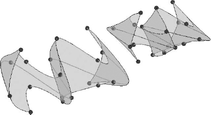
Keep in mind that selecting all the splines and then creating the surface will result in very different forms than if you were to sequentially select only adjacent splines (Figure 9.39). The result is that the surface form isn't interpolated as smooth between the upper and lower splines. Instead, a distinct edge is created between the two splines.
FIGURE 9.39 Spline-based surfaces
As you can see, it's easy to create complex surface forms in Revit using reference lines. Now let's begin to create complex forms using reference planes.
MASSING FORMS
As discussed earlier, creating solid masses isn't done by creating a particular type of form and then entering Sketch mode. Creating the necessary references and then evoking the Create Form tool creates mass forms.
First, you don't have to create solid forms. You can also create surfaces, not only from lines but also from closed loops. Figure 9.40 illustrates this.
FIGURE 9.40 Surface or form option

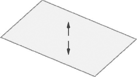
Even if you create a surface, you'd still have the option to convert it into a solid mass (Figure 9.41) by selecting the surface and using the control arrows to pull the surface into a three-dimensional shape.
FIGURE 9.41 Creating a solid from a surface
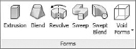
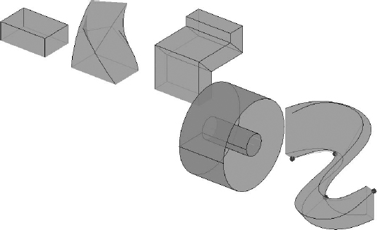
Now let's create each of the reference shapes necessary to create each of the familiar forms in Revit (Figure 9.42). From left to right, these shapes will create Extrusions, Blends, Sweeps, Revolves, and Swept Blends.
Figure 9.43 shows the resulting forms that are created from each of the references. You could also create voids from the same reference shapes. If you want to download this file for further investigation, it's named c09_Massing_Types.rvt.
FIGURE 9.42 Using reference shapes to create forms

FIGURE 9.43 Resulting mass forms
All of these mass forms contain parameters and controls relative to their form. We'll now explain how to create surface and solid forms intuitively in the project environment.