
Annotating with Tags
Tags are text labels for elements such as doors, walls, windows, rooms, and several other objects that architects typically need to reference in a set of drawings. These tags typically refer to other schedules or information in other portions of the drawing set and are unique to the view they are inserted within. In Revit, tags are intelligent, bidirectional symbols that report information stored in an object's properties. You can enter a value directly into the family properties or right into the tag itself.
Once you've tagged an element and given the tag a value, the element will retain that value until you remove it. The value lives with the elements within Revit; it is not a property of the tag. That means you can delete or remove tags without fear of losing the data entered into the tag. It also means that once an element is tagged with information in one view, the same element will report the same information in any other view that it is tagged in without you having to have the information entered twice. To explain this a bit better, take the example of a door tag.
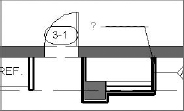
You've placed a door tag in a view. The tag initially had “?” as a value, meaning that the door number was blank. You've entered a door number of 3-1. In another view, you can now tag the same door and have it automatically display a value of 3-1. You can also delete any, or even all, of the door tags for that door and have new tags you place also report the door number of 3-1.

Keep in mind that you can also tag elements that are in linked models. While you cannot edit the properties of these elements (e.g., you cannot change the wall type or door number), you can add tags to any of the linked elements as you can if the same elements were part of your project file.
Tags are versatile elements in Revit. A tag can display a door number, but it can just as easily display any other properties of the door, such as fire rating, cost, or material type.
Inserting Tags
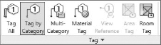
Tags can be automatically inserted when another element, such as a door or room, is placed within the model (by checking the Tag On Placement option in the Options Bar), or they can be inserted later in the project. The options to place a tag are all located on the Tag panel of the Annotate tab (Figure 19.31).

When you're adding tags, it's not necessary to find or choose the right tag—Revit will do that for you. Tag types are specific to the elements to which they are being tagged. For example, you can use a door tag to tag a door, but you can't use a door tag to tag a wall or other element within Revit. Figure 19.32 shows you some of the tags that are available; there is a tag for each type of object within Revit. You can customize each of the tag family types so you can graphically differentiate your door tags from wall tags, room tags, area tags, and so on.

When inserting the tag, you'll have several options regarding tag placement available in the Options Bar (Figure 19.33):
FIGURE 19.33 The Options Bar when placing a tag
![]()
Orientation The first option allows you to orientate the tag horizontally or vertically. Tags, like text, will always read from either the bottom or right side of the sheet or view.
The Tags Button Clicking this button opens the Tags dialog box, where you can load various tags.
Leader The final three options deal with the tag leader. You can check the Leader check box on (or off) to have a leader show (or not show). While attached leaders are the default for Revit tags, the Attach End drop-down can be changed to not associate the end of the leader with the element you've selected. Using the Unattached End option allows the leader to float free of the object. The final option of this set for leaders is the default leader length. By default, the value is set to ½″. When you're placing tags like wall tags that have leaders perpendicular to the wall they are tagging, it is a good idea to set a default length you are comfortable with. You can adjust the tag location after inserting them, but sometimes it's easier to set a good default value in leader length.
Using the Tag Toolbox
![]() On the Annotate tab, you'll find there are several methods you can use to insert tags into Revit. Each of these tools allows you to tag elements within a view in different ways. Each has different uses and can be used in conjunction or separately to help document your project.
On the Annotate tab, you'll find there are several methods you can use to insert tags into Revit. Each of these tools allows you to tag elements within a view in different ways. Each has different uses and can be used in conjunction or separately to help document your project.
Tag By Category The Tag By Category button is possibly one of the most frequently used Tag commands. As we mentioned before, several tags are available in Revit, allowing you to tag a host of elements in the model. Click the Tag By Category button (shown in Figure 19.34) when you want to tag one element at a time, regardless of its category.
FIGURE 19.34 Tag By Category button
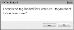
Using this tag command will allow you to select a door, a window, a wall—whatever single element you want to apply a tag to in the model. As you hover over elements, Revit will show the tag that corresponds to that element, allowing you to place it. Should the element you are trying to tag not have the associated tag loaded in the Revit file, Revit will prompt you to load it (Figure 19.35). You'll be presented with a dialog box asking you to load a tag, which you can do either from Revit's default stock or your own office library.
Tag All The Tag All command (Figure 19.36) will do exactly that—tag all the elements within a given view.

Tagging all the elements, however, doesn't mean that you have to tag everything within a view. That would be messy since everything within your view gets a tag. Revit will tag elements by the groups that you select. So, for example, you can tag all the doors. Or you can tag all doors, walls, and rooms—or any combination of any list of elements. When you select the Tag All command, Revit will present you with the Tag All Not Tagged dialog box (Figure 19.37). This dialog box displays a list of the elements in the view for which you have already loaded tags. Here, you can specify which elements can get tagged, what tag will be used, and if that tag will have a leader assigned to it. Use the Ctrl key on your keyboard to select more than one element from the list. When you've selected the categories you would like tagged, click OK.
FIGURE 19.37 Tag All Not Tagged dialog box

Tagging all the elements within a view can be a wondrous time-saver—but only if you're OK with Revit choosing the location for each of the tags. In some cases, like rooms, Revit will place the tags in the middle of the rooms. For most spaces, that will work just fine. For other tag types, such as walls or doors, you might have to adjust tag locations to make sure everything reads properly.
Room Tag and Area Tag These two tag types work in much the same way. They will tag the room elements or area elements, depending on the type of view you happen to be in. In the case of Figure 19.38, we are in a plan view that has no areas, so only the Room tag is active. To tag rooms or areas, simply select the tag type you want and select the room or area object. By default, when you place rooms or areas initially, Revit will automatically tag them for you.
FIGURE 19.38 Room and Area tags

Material Tag The Material tag (Figure 19.39) is an interesting tag type that can best be described as a hybrid between text and a keynote.
FIGURE 19.39 The Material Tag tool

This tag is actually a text box and leader, much like the Text command, and like Text, it will allow you to type a value into the text box. Like a keynote, the material that you tag will remember its note and the next time you tag an element, it will produce that same text. Change the text in one location and it will change it everywhere. To make this a bit clearer, let's use an example. From the book's web page, download the Jenkins.rvt file for Chapter 19, and then follow these steps:
- Open one of the floor plans. In our example, we've chosen Level 3.
- Choose the Material tag from the Annotate tab. Hovering over one of the existing, exterior walls, you'll see a question mark, as shown in Figure 19.40.
FIGURE 19.40 Tagging the exterior wall material
- Place the tag and type EXISTING MASONRY WALL in the text box. Then click to insert a new tag.
- As you hover over some of the interior walls, you'll notice that Revit will present you with the question mark, indicating materials that are not yet defined. Hover over the exterior wall, however, and you'll notice that the tag value automatically fills itself in (Figure 19.41).
FIGURE 19.41 Material tags keep their value.

Using these tag types can be a good alternative to using the Revit keynote system. This allows you some versatility over the note—you can type the text when adding the note—while also ensuring consistency across the project. This tag type only works with materials and can't be used on detail components or any linework.
Multi-Category Tag The Multi-Category tag allows you to use the same tag style in a project to tag elements of different categories (Figure 19.42).
FIGURE 19.42 The Multi- Category tag

This tag type can be useful in a number of ways. Let's say you want to tag several elements in a floor plan and call out their manufacturer and unit cost. Historically, you would have to create a few different tags to tag Furniture, Systems Furniture, Casework, and any other category you had wanted to tag. Now, a single tag type can do this for you. Let's step through making a Multi-Category tag.
From the book's web page, download the JenkinsMusicBldg.rvt file for Chapter 19. Then follow these steps:
- Open one of the floor plans. In our example, we've chosen Level 3.
- Click the Application menu and choose New
 Family. This will take you to the default Revit family templates. Open the Annotation folder and choose Multi-Category Tag.rft.
 - In the Family Editor, place a label. Once the label is located on the screen, the Edit Label dialog box opens. Here you'll see a long list of the family categories that are common across multiple family types—Assembly Code, Cost, Family Name, and Model, among others. The full list is shown in the Edit Label dialog box in Figure 19.43. To make our simple tag, select Manufacturer and Cost.

- Finish the family and load it into the project.
- Now, select an element in the floor plan. In our example, we've already chosen the dining room table, but you can choose another element, like a chair or another piece of furniture. When the tag is placed, you will see the familiar question mark, indicating this element has no predefined value for either Manufacturer or Cost. Place the tag and double-click the question mark.
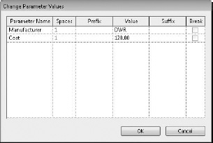
- The Change Parameter Values dialog box (Figure 19.44) opens. Enter a value for both Manufacturer and Cost, and then click OK.
FIGURE 19.44 Changing the parameter value
- As you hover your mouse over other elements in this view, you'll notice the same behavior as with other tags. Elements that have predefined values will show the tag filled in while other elements without values will have question marks. Add a few more tags, and you can begin to see some of the versatility of the Multi-Category tag.