
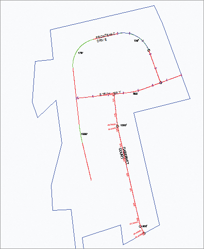
Alignments in Civil 3D can be created from AutoCAD objects (lines, arcs, or polylines) or by layout. This section looks at both ways to create an alignment and discusses the advantages and disadvantages of each. The exercise will use the street layout shown in Figure 6-4 as well as the different methods to achieve your designs.
Figure 6-4: Proposed street layout

Creating from a Line, Arc, or Polyline
Most designers have used either polylines or lines and arcs to generate the horizontal control of their projects. It’s common for surveyors to generate polylines to describe the center of a right of way or for an environmental engineer to draw a polyline to show where a new channel should be constructed. These team members may or may not have Civil 3D, so they use their familiar friends—the line, arc, and polyline—to describe their design intent.
Although these objects are good at showing where something should go, they don’t have much data behind them. To make full use of these objects, you should convert them to native Civil 3D alignments that can then be shared and used for myriad purposes. Once an alignment has been created from a polyline, offsets can be created to represent rights of way, building lines, and so on. In this exercise, you’ll convert a polyline to an alignment and create offsets:
1. Open the AlignmentsFromPolylines.dwg file. You can download this file from www.sybex.com/go/masteringcivil3d2012. You see the red polylines representing the center of roads, right of ways, and parcels.
2. Change to the Home tab and choose Alignment Create Alignment From Objects.
3. Pick the polyline labeled Syrah Way, shown previously in Figure 6-4, and press ↵. Press ↵ again to accept the default direction; the Create Alignment From Objects dialog appears.
4. Change the Name field to Syrah Way, and select the Centerline type, as shown in Figure 6-5.
Figure 6-5: The settings used to create the Syrah Way alignment
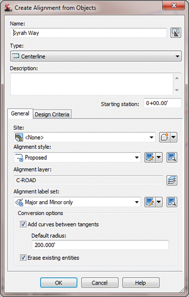
5. Accept the other settings, and click OK.
The Create Alignment From Objects Dialog
In the Create Alignment From Objects dialog (Figure 6-5), there are many settings that you can use to create an alignment:
Name This is the alignment name. No alignment name can be duplicated in a drawing.
Type The alignment types can be thought of as places for objects that are alike. They can react differently depending on which type is selected.
Centerline Used mainly for centers of roads, streams, swales, etc. It places this type of alignment in the Alignments Centerline Alignments collection.
Offset Used for offset alignments. The difference between this and the centerline alignment is that you have the option in Alignment properties to set Offset parameters, such as naming a parent alignment and offset values. It places this alignment in the Alignments Offset Alignments collection.
Curb Return Used for curb returns. The difference between this and the offset alignment is that instead of offset, you have the option in Alignment properties to set Curb Return parameters, such as setting two parent alignments and offsets. It places this type of alignment in the Alignments Curb Return Alignments collection.
Miscellaneous This is a stripped-down alignment type that only contains Information, Stationing, and Masking tabs. It places this alignment type in the Alignments Miscellaneous Alignments collection.
The General tab contains the following options:
Description You can be verbose here to describe your alignment.
Starting Station Setting this with a number, either positive or negative, will be the starting stationing for the alignment. This is handy if you need to start your alignment to coincide with existing stationing, or if you wish to have your 0+00 stationing at an intersection of a road.
Site A place to keep Civil 3D objects that you want to interact with each other. As previously mentioned, all of our alignments are put on the <None> site.
Alignment Style You can set different styles to visually show your alignment. For more on styles, refer to Chapter 19, “Styles.”
Alignment Layer Overrides the layer that is specified in Settings for alignments.
Alignment Label Set As with the Alignment style, you can visually select your labels.
Conversion Options Depending on your selections, these will add curves or erase the original entities.
The Design Criteria tab contains:
Starting Design Speed Specify the design speed of the road by typing in a value or by using design criteria such as the American Association of State Highway and Transportation Officials (AASHTO)’s 2001 design manual. You can also set rules, or expressions for minimum radius, lengths, deflections, and spiral checks. The design constraints and check sets will be covered later in this chapter.
You’ve created your first alignment and attached stationing and geometry point labels. It is common to create offset alignments from a centerline alignment to begin to model rights of way. In the following exercise, you’ll create offset alignments and mask them where you don’t want them to be seen:
1. Change to the Home tab and choose Alignment Create Offset Alignments.
2. Pick the Syrah Way alignment to open the Create Offset Alignments dialog shown in Figure 6-6.
Figure 6-6: The Create Offset Alignments dialog
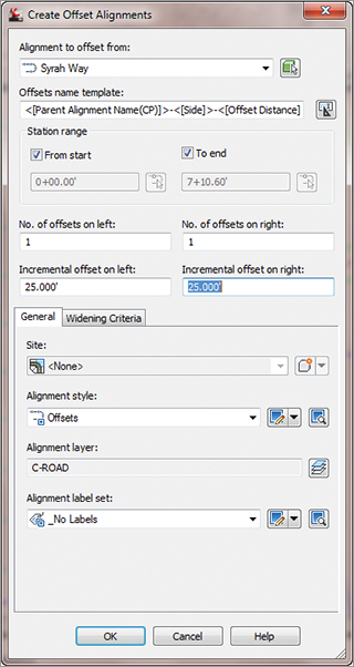
3. Change the Incremental offset on the left to 25′. Change the Incremental offset on the right to 25′. Click OK to accept the rest of the defaults, as shown in Figure 6-6.
4. Select the offset alignment just created along the northerly right of way of Syrah Way.
5. Choose Alignment Properties from the Modify panel to open the Alignment Properties dialog.
6. Change to the Masking tab and click the Add Masking Region button to open the dialog shown in Figure 6-7. Type 0+95.00′ for the first station and 1+95.00′ for the second station when prompted. Click OK. Notice that the alignment is now masked at the intersection of Syrah Way and Frontenac Drive at the east end.
Figure 6-7: Creating an alignment mask

7. Repeat the process for the rest of the intersections, starting at the end of the arc on both right-of-way alignments on Syrah Way.
Note that when you selected the beginning and end of the offset alignment, the Lock To Start and Lock To End boxes were checked automatically.
Offset alignments are simple to create, and they are dynamically linked to a centerline alignment. To test this, grip the centerline alignment, select the endpoint grip, and stretch the alignment to the west. Notice the change.
Offset Grips and More
Offset alignments have two special grips: the arrow and the plus sign. The arrow is used to change the offset value, and the plus sign is used to create a transition, called a widening, such as a turning lane. The Create Widening command can be found in the Alignment drop-down on the Create Design panel of the Home tab. Widening criteria can also be found in the Create Offset Alignments dialog.
Even offset alignments with widening remain dynamic to their host alignment. Offset alignment objects can be found in Prospector in the Alignments collection.
You created an alignment from polylines and two offsets. It’s ready for use in corridors, in profiling, or for any number of other uses.
Creating by Layout
Now that you’ve made an alignment from polylines, let’s look at the other creation option: Create By Layout. You’ll use the same street layout (Figure 6-4) that was provided by a planner, but instead of converting from polylines, you’ll trace the alignments. Although this seems like duplicate work, it will pay dividends in the relationships created between segments:
1. Open the AlignmentsbyLayout.dwg file. You see the lines and arcs used to create the center of roads. The arc sections are the color green and the line sections are the color red. Everything else has been removed for clarity.
2. Change to the Home tab and choose Alignment Alignment Creation Tools from the Create Design panel. The Create Alignment – Layout dialog appears, as shown in Figure 6-8.
Figure 6-8: Create Alignment – Layout dialog

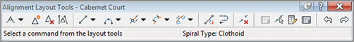
3. Change the Name field to Cabernet Court if it is not already set, and then click OK to accept the other settings as shown in Figure 6-8. The Alignment Layout Tools toolbar appears (Figure 6-9).
Figure 6-9: The Alignment Layout Tools toolbar
4. Click the down arrow next to the Draw Tangent-Tangent Without Curve tool at the far left, and select the Tangent-Tangent (With Curves) option (see Figure 6-10). The tool places a curve automatically; you’ll adjust the curve, watching the tangents extend as needed.
Figure 6-10: The Tangent-Tangent (With Curves) tool

5. Using the circles as guides, pick the southernmost center of the circle of Cabernet Court using a center snap.
6. Continue to pick the center of the other three circles to finish creating this alignment. Press ↵ to end the command. Your drawing should look similar to Figure 6-11.
Figure 6-11: Completing the Cabernet Court alignment
7. Click the red X button at the upper-right on the toolbar to close it.
Zoom in on the lower arc. Notice that it follows closely with the desired arc radius. Now zoom in on the upper arc, and notice that it doesn’t match the arc the planner put in for you to follow. That’s OK—you’ll fix it in a few minutes. It bears repeating that in dealing with Civil 3D objects, it’s good to get something in place and then refine. With Land Desktop or other packages, you didn’t want to define the object until it was fully designed. In Civil 3D, you design and then refine.
The alignment you just made is one of the most basic. Let’s move on to some of the others and use a few of the other tools to complete your initial layout. In this exercise, you build the alignment at the north end of the site, but this time you use a floating curve to make sure the two segments you create maintain their relationship:
1. Change to the Home tab and choose Alignment Alignment Creation Tools from the Create Design panel. The Create Alignment – Layout dialog appears.
2. In the Create Alignment – Layout dialog, do the following:
- Change the Name field to Frontenac Drive.
- Set the Alignment Style field to Layout.
- Set the Alignment Label Set field to Major And Minor Only.
3. Click OK, and the Alignment Layout Tools toolbar appears.
4. Select the Draw Fixed Line – Two Points tool.
5. Pick the two points circled in Figure 6-12, using Endpoint snaps and working south to north to draw the fixed line. When you’ve finished, the command line will state Specify start point:.
Figure 6-12: Pick the two points circled on Frontenac Drive.

6. Click the down arrow next to the Add Fixed Curve (Three Points) tool on the toolbar, and select More Floating Curves Floating Curve (From Entity End, Through Point), as shown in Figure 6-13.
Figure 6-13: Selecting the Floating Curve tool

7. Ctrl+click the fixed-line segment you drew in steps 4 and 5. A blue rubber band should appear, indicating that the alignment of the curve segment is being floated off the endpoint of the fixed segment (see Figure 6-14). The Ctrl+click is required to make the pick activate the alignment segment and not the polyline entity.
Figure 6-14: Adding a floating curve to the Frontenac Drive alignment

8. Pick the endpoint of the arc of the Frontenac Drive polyline arc segment.
9. Right-click or press ↵ to exit the command.
10. Close the toolbar to return to Civil 3D.
Pick the Frontenac Drive alignment and then pick the grip on the upper end of the line and pull it away from its location. Notice that the line and the arc move in sync, and tangency is maintained (see Figure 6-15).
Figure 6-15: Floating curves maintain their tangency.
Best Fit Alignments from Lines and Curves
The Create Best Fit Alignment command can use AutoCAD blocks, entities, points, COGO points, or Feature lines. You can also simply click on the screen. The Line and Curve drop-down menus on the Alignment Layout toolbar include options for Floating and Fixed Lines by Best Fit, as well as Best Fit curves in all three flavors: Fixed, Float, and Free. These options are helpful when you’re doing rehab work or other jobs where some form of the data already exists. It is similar to what we covered in Chapter 1 in the “Best Fit Entities” section. Let’s see how it works with alignments:
1. Open the AlignmentsBestFit.dwg file, which you can download from this book’s web page.
2. From the Home tab and Create Design panel, choose Alignment Alignment Creation Tools. The Create Alignment – Layout dialog appears.
3. Enter Best Fit Lines in the Name field. Leave the rest at their defaults and click OK. The Alignment Layout Tools – Best Fit Lines palette opens.
4. Click the down arrow next to the Draw Fixed Line – Two Points tool on the toolbar, and select the Fixed Line – Best Fit option, as shown in Figure 6-16. The Tangent By Best Fit dialog opens (Figure 6-17).
Figure 6-16: Selecting Fixed Line – Best Fit

Figure 6-17: The Tangent By Best Fit dialog
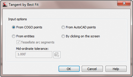
Here, you can choose various methods to create a best fit line alignment: From COGO points, From Entities, From AutoCAD points, or by clicking on the screen.
5. Pick the By Clicking On The Screen radio button and click OK.
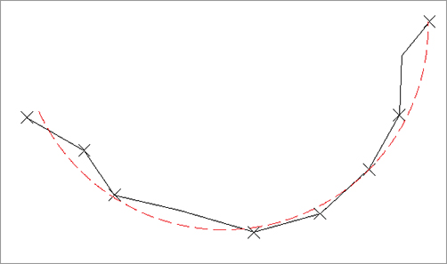
6. With the running endpoint osnap, click on all the endpoints of the line. As you progress, you see a red dashed line being formed. In your selections, this line looks at all the endpoints selected in order to create the best fit line alignment (Figure 6-18). When you get to the last endpoint, press ↵ to open the Regression Data window.
Figure 6-18: The best fit line being formed

7. In the Regression Data window, you can choose to exclude endpoints, or force them to be a pass-through endpoint by checking the boxes. As you do, notice the changes that occur on your best fit line alignment (Figure 6-19).
Figure 6-19: Regression Data window

8. Click the green check mark on the upper right-hand side of the Regression Data window to accept and dismiss the window. The alignment is complete.
The best fit alignment by curve works the same way as the Best Fit Line option, as shown in Figure 6-20.
Figure 6-20: The best fit curve
Reverse Curve Creation
Next, let’s look at a more complicated alignment construction—building a reverse curve connecting two curves:
1. Open the AlignmentReverse.dwg file.
2. Change to the Home tab and choose Alignment Alignment Creation Tools from the Create Design panel. The Create Alignment – Layout dialog appears.
3. In the Create Alignment – Layout dialog, do the following:
- Change the Name field to Reverse.
- Set the Alignment Style field to Layout.
- Set the Alignment Label Set field to Major Minor And Geometry Points.
4. Click OK, and the Alignment Layout Tools toolbar appears.
5. Start by drawing a fixed line from the north end of the western portion to its endpoint using the same Draw Fixed Line (Two Points) tool as before.
6. Use the Floating Curve (From Entity, Radius, Through Point) tool to draw a curve from the end of this segment.
7. At the Specify radius <200>: prompt, enter 500.
8. At the Is curve solution angle [Greaterthan180/Lessthan180] <Lessthan180>: prompt, press ↵.
9. Click on the other end of the arc.
10. The command continues. Select the arc.
11. The second arc radius is 400′ and it is less than 180.
12. The command now prompts: Is curve compound or reverse to curve before? [Compound/Reverse] <Compound>:. Type R↵ to specify that it is a reverse curve.
13. Click the endpoint of the lower arc and then continue to finish the alignment by selecting the two-point line (Figure 6-21).
Figure 6-21: Segment layout for the Reverse Curve alignment

The alignment now contains a perfect reverse curve. Move any of the pieces, and you’ll see the other segments react to maintain the relationships shown in Figure 6-22. This flexibility in design isn’t possible with the converted polylines you used previously. Additionally, the flexibility of the Civil 3D tools allows you to explore an alternative solution (the reverse curve) as opposed to the basic solution. Flexibility is one of Civil 3D’s strengths.
Figure 6-22: Curve relationships during a grip-edit

You’ve completed your initial layout. There are some issues with curve sizes, and the reverse curve may not be acceptable to the designer, but you’ll look at those changes later in the section “Component Level Editing.”
Creating with Design Constraints and Check Sets
Starting in Civil 3D 2009, users have the ability to create and use design constraints and design check sets during the process of aligning and creating design profiles. Typically, these constraints check for things like curve radius, length of tangents, and so on. Design constraints use information from AASHTO or other design manuals to set curve requirements. Check sets allow users to create their own criteria to match local requirements, such as subdivision or county road design. First, you’ll make one quick set of design checks:
1. Open the CreatingChecks.dwg file.
2. Change to the Settings tab in Toolspace, and expand the Alignment Design Checks menu branch.
3. Right-click the Line Folder, and select New to display the New Design Check dialog.
4. Change the name to Subdivision Tangent.
5. Click the Insert Property drop-down menu, and select Length.
6. Click the greater-than/equals symbol (>=), and then type 100 in the Expression field as shown. When complete, your dialog should look like Figure 6-23. Click OK to close the dialog.
Figure 6-23: The completed Subdivision Tangent design check. The result of a design check is true or false; in this case, it tells you whether the alignment line segment is equal to or longer than 100′.

7. Right-click the Curve folder, and create the Subdivision Curve design check, as shown in Figure 6-24.
Figure 6-24: The completed Subdivision Curve design check. The >= indicates that an acceptable curve is equal to or greater than 200′. Without the equal portion, a curve would require a radius of 200.01′ to pass the check.

8. Right-click the Design Check Sets folder, and select New to display the Alignment Design Check Set dialog.
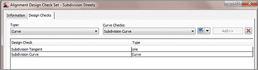
9. Change the name to Subdivision Streets, and then switch to the Design Checks tab.
10. Click the Add button to add the Subdivision Tangent check to the set.
11. Choose Curve from the Type drop-down list, and click Add again to complete the set as shown in Figure 6-25.
Figure 6-25: The completed Subdivision Streets design check set
Once you’ve created a number of design checks and design check sets, you can apply them as needed during the design and layout stage of your projects.
Design Checks versus Design Criteria
In typical fashion, the language used for this feature isn’t clear. What’s the difference? A design check uses basic properties such as radius, length, grade, and so on to check a particular portion of an alignment or profile. These constraints are generally dictated by a governing agency based on the type of road involved. Design criteria use speed and related values from design manuals such as AASHTO to establish these geometry constraints.
Think of having a suite of check sets, with different sets for each city and type of street or each county, or for design speed. In the next exercise, you’ll see the results of your Subdivision Streets check set in action:
1. Open the CheckingAlignments.dwg file.
2. Change to the Home tab and choose Alignment Alignment Creation Tools from the Create Design tab. The Create Alignment – Layout dialog appears.
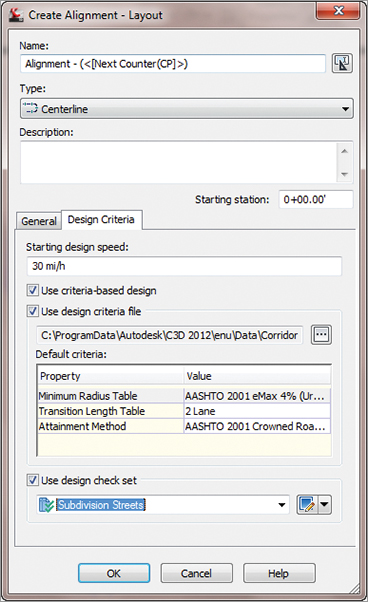
3. Click the Design Criteria tab, and set the design speed to 30 mi/h, as shown in Figure 6-26. Set the check boxes as shown in the figure. (Note that the Use Criteria-Based Design check box must be selected to activate the other two.) Click OK to close the dialog.
Figure 6-26: Setting up design checks during the creation of alignments
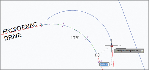
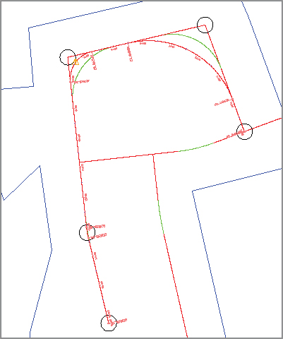
4. Select the Tangent-Tangent With Curves option on the left side of the Alignment Layout toolbar. The curve radius on the northernmost part of Frontenac Drive is 175′ and is left in place to illustrate the design check failure indicators.
5. Connect the center points of the circles on the screen to create the alignment shown in Figure 6-27. Notice the exclamation-point symbol, which indicates that a design check has been violated.
Figure 6-27: Completed alignment layout
Now that you know how to create an alignment that doesn’t pass the design checks, let’s look at different ways of modifying alignment geometry. As you correct and fix alignments that violate the assigned design checks, those symbols will disappear.