
Creating an Interference Check between a Storm and Sanitary Pipe Network
In design, you must make sure pipes and structures have appropriate separation. You can perform some visual checks by rotating your model in 3D and plotting pipes in profile and section views (see Figure 13-69). Civil 3D also provides a tool called Interference Check that makes a 3D sweep of your pipe networks and lets you know if anything is too close for comfort.
Figure 13-69:(Top) Two pipe networks may interfere vertically where crossings occur. (Bottom) Viewing your pipes in profile view can also help identify conflicts.

The following exercise will lead you through creating a pipe network Interference Check to scan your design for potential pipe network conflicts:
1. Open the InterferenceStart.dwg file. The drawing includes a sanitary sewer pipe network and a storm drainage network.
2. Select a part from either network and choose Interference Check from the Analyze panel. You’ll see the prompt Select a part from the same network or different network:. Select a part from the network not chosen.
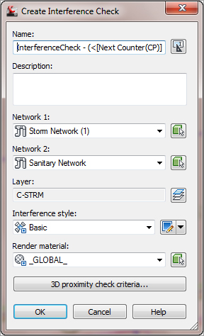
3. The Create Interference Check dialog appears (Figure 13-70). Name the Interference Check Exercise, and confirm that Sanitary Sewer Network and Storm Network appear in the Network 1 and Network 2 boxes.
Figure 13-70: The Create Interference Check dialog
4. Click 3D Proximity Check Criteria, and the Criteria dialog appears (see Figure 13-71).
You’re interested in finding all network parts that are within a certain tolerance of one another, so enter 3.000′ (0.91 m) in the Use Distance box. This setting creates a buffer to help find parts in all directions that might interfere.
Figure 13-71: Criteria for the 3D proximity check

If you were interested only in physical, direct collisions between parts in your networks, leave the Apply 3D Proximity Check check box deselected and dismiss this dialog.
An Interference Cloud?
Think of the Interference Check as if each part is surrounded by a 3D “cloud.” When that cloud touches another part, interference is flagged. If you specify distance, such as 2′ (0.61 m), your cloud is created 2′ (0.61 m) in all directions around each part. When you specify scale, such as 1.5, your cloud makes each part 1.5 times larger than its actual size.
5. Click OK to exit the Criteria dialog, and click OK to run the Interference Check. You see a dialog that alerts you to two interferences. Click OK to dismiss this dialog.
6. Zoom in on the crossing of pipes of CB3 and CB6 (Storm Network) and the crossing sanitary pipe. A small marker has appeared, as shown in Figure 13-72.
Figure 13-72: The interference marker in plan view

7. From the View control, select SW Isometric. Zoom in on the crossing of pipes of CB3 and CB6 and the crossing sanitary pipe. The interference marker appears in 3D, as shown in Figure 13-73.
Figure 13-73: The interference marker in 3D

8. Using the same view navigation technique as you used in step 7, change back to a top-view orientation.
9. Drill into the Pipe Networks branch of Prospector, and you see an entry for Interference Checks. Note that each instance of interference is listed in the preview pane for further study. Making edits to your pipe network flags the interference check as “out of date.” You can rerun Interference Check by right-clicking Interference Check in Prospector. You can also edit your criteria in this right-click menu.