
Once alignments are sampled, volumes can be calculated from the sampled surface or from the corridor section shape. These volumes are calculated in a materials list and can be displayed as a label on each section view or in an overall volume table, as shown in Figure 12-17.
Figure 12-17: A total volume table inserted into the drawing

The volumes can also be displayed in an XML report, as shown in Figure 12-18.
Figure 12-18: A total volume XML report shown in Microsoft Internet Explorer

Once a materials list is created, it can be edited to include more materials or to make modifications to the existing materials. For example, soil expansion (fluff or swell) and shrinkage factors can be entered to make the volumes more accurately match the true field conditions. This can make cost estimates more accurate, which can result in fewer surprises during the construction phase of any given project.
Creating a Materials List
Materials can be created from surfaces or from corridor shapes. Surfaces are great for earthwork because you can add cut or fill factors to the materials, whereas corridor shapes are great for determining quantities of asphalt or concrete. In this exercise, you practice calculating earthwork quantities for the Cabernet Court corridor:
1. Continue working in sections1.dwg, or you can open the sections4.dwg file.
2. Change to the Analyze tab and choose Compute Materials from the Volumes And Materials panel. The Select A Sample Line Group dialog appears.
3. In the Select Alignment field, verify that the alignment is set to Cabernet Court.
4. Click OK. The Compute Materials dialog appears.
5. Select Earthworks from the drop-down menu in the Quantity Takeoff Criteria drop-down box.
6. Click the Object Name cell for the Existing Ground surface, and select EG from the drop-down menu.
7. Click the Object Name cell for the Datum surface, and select Concord Commons Corridor Concord Commons Datum (this is the name of the corridor followed by the name of the surface) from the drop-down menu.
8. Verify that your settings match those shown in Figure 12-19.
Figure 12-19: The settings for the Compute Materials dialog
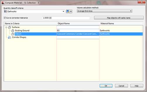
9. Click OK.
10. Save the drawing.
Creating a Volume Table in the Drawing
In the preceding exercise, materials were created that represent the total dirt to be moved or used in the sample line group. In the next exercise, you insert a table into the drawing so you can inspect the volumes:
1. Continue using the sections4.dwg file (or sections1.dwg if you’re working in that).
2. Change to the Analyze tab and choose Total Volume Table from the Volumes And Materials panel. The Create Total Volume Table appears.
3. Verify that your settings match those shown in Figure 12-20. Pay close attention and make sure that Reactivity Mode at the bottom of the dialog is set to Dynamic. This will cause the table to update if any changes are made to the sample line collection.
Figure 12-20: The Create Total Volume Table dialog settings
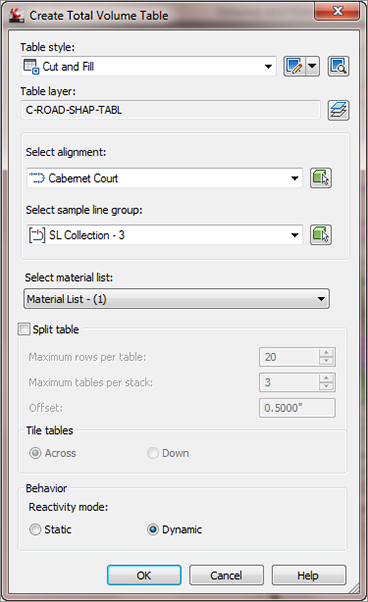
4. Click OK.
5. Pick a point in the drawing to place the volume table. The table indicates a Cumulative Fill Volume of 247.62 cubic yards and a Cumulative Cut Volume of 2,120.18 cubic yards, as shown in Figure 12-21. This means you will have to haul off just over 1,870 cubic yards of dirt, or about five tri-axle truckloads from the site during road construction. This might not seem like a lot, but we have only analyzed one roadway and the actual lot grading can increase that number.
Figure 12-21: The total volume table

6. Save the drawing.
Adding Soil Factors to a Materials List
Because this design obviously has an excessive amount of fill, the materials need to be modified to bring them closer in line with true field numbers. For this exercise, the shrinkage factor will be assumed to be 0.80 and 1.20 for the expansion factor (20 percent shrink and swell). These numbers are arbitrary—numbers used during an actual design will be based on soil type and conditions. In addition to these numbers (which Civil 3D represents as Cut Factor for swell and Fill Factor for shrinkage), you can specify a Refill Factor value. This value specifies how much cut can be reused for fill. For this exercise, assume a Refill Factor value of 1.00:
1. Continue using drawing sections4.dwg.
2. Change to the Analyze tab and choose Compute Materials from the Volumes And Materials panel. The Select A Sample Line Group dialog appears.
3. Select the Cabernet Court alignment and the SL Collection – 3 sample line group, if not already selected.
4. Click OK. The Edit Material List dialog appears.
5. Enter a Cut Factor of 1.20 and a Fill Factor of 0.80, and verify that all other settings are the same as in Figure 12-22. Click OK.
Figure 12-22: The Edit Material List dialog

6. Examine the Total Volume table again. Notice that the new Cumulative Fill Volume is 198.09 cubic yards and the new Cumulative Cut Volume is 2,544.22 cubic yards.
7. Save the drawing.
Can You Have Accurate Volume Numbers Without Sections?
Yes, you can. Civil 3D has the capability to add cut and fill factors to both volume surfaces during creation and in the surface volumes panorama.
Volumes can also be created in a format that can be printed and put into a project documentation folder. This is accomplished by creating a volume report, which is populated through LandXML. This report will open and display in your browser, but you can convert it to Word or Excel format with a simple copy and paste from the XML report. The XML report style sheet can be edited. The following is a sample of the default code in the style sheet:
- <CrossSect name="1+00.00" number="2"
 sta="100" staEq="100" areaCut="160.05542428531"
areaUsable="160.05542428531" areaFill="0"
volumeCut="176.470710087465"
volumeUsable="176.470710087465"
volumeFill="0" cumVolumeCut="176.470710087465"
cumVolumeUsable="176.470710087465" cumVolumeFill="0"
massHaul="176.470710087465">
- <MaterialCrossSects>
- <MaterialCrossSect name="Earthworks(Cut)"
area="160.05542428531" volume="176.470710087465"
cumVolume="176.470710087465">
- <MaterialCrossSectEnvelop area="160.05542428531">
  <CrossSectPnt OE="-25.000000, 798.700342" />
  <CrossSectPnt OE="-25.000000, 799.308899" />
  <CrossSectPnt OE="-18.636164, 799.554025" />
  <CrossSectPnt OE="-12.983610, 800.034982" />
  <CrossSectPnt OE="-7.134326, 800.364341" />
  <CrossSectPnt OE="0.000000, 800.542347" />
  <CrossSectPnt OE="11.591210, 800.831555" />
  <CrossSectPnt OE="12.106582, 800.844414" />
  <CrossSectPnt OE="25.000000, 801.248116" />
  <CrossSectPnt OE="24.000000, 798.477101" />
  <CrossSectPnt OE="20.000000, 798.064101" />
  <CrossSectPnt OE="18.000000, 798.357101" />
  <CrossSectPnt OE="16.000000, 796.383767" />
  <CrossSectPnt OE="0.000000, 796.803185" />
  <CrossSectPnt OE="-16.000000, 796.587009" />
  <CrossSectPnt OE="-18.000000, 798.560342" />
  <CrossSectPnt OE="-20.000000, 798.600342" />
  <CrossSectPnt OE="-24.000000, 798.347342" />
  <CrossSectPnt OE="-25.000000, 798.700342" />
  </MaterialCrossSectEnvelop>
  </MaterialCrossSect>
Generating a Volume Report
Volume reports can be included on a drawing but normally aren’t because of liability issues. However, it is often necessary to know what these volumes are and have some record of them. Civil 3D provides you with a way to create a report that is suitable for printing or for transferring to a word processing or spreadsheet program. In this exercise, you’ll create a volume report for the Concord Commons corridor:
1. Open the sections5.dwg file.
2. Change to the Analyze tab and choose Volume Report from the Volumes And Materials panel. The Report Quantities dialog appears.
3. Verify that Material List – (1) is selected in the dialog and click OK.
4. You may get a warning message that says “Scripts are usually safe. Do you want to allow scripts to run?” Click Yes.
5. Note the cut-and-fill volumes and compare them to your volume table in the drawing. Close the report when you are done viewing it.
6. Close the drawing without saving.