
Once you’ve designed your network, it’s important to annotate the design in a pleasing way. This section focuses on pipe network–specific label components in plan and profile views (see Figure 13-66).
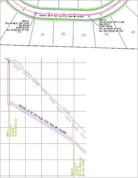
Figure 13-66: Typical pipe network labels (top) in plan view and (bottom) in profile view
Like all Civil 3D objects, the Pipe and Structure label styles can be found in the Pipe and Structure branches of the Settings tab in Toolspace and are covered in Chapter 19.
Creating a Labeled Pipe Network Profile Including Crossings
This exercise will apply several of the concepts in this chapter to give you hands-on experience producing a pipe-network profile that includes pipes that cross the alignment:
1. Open the Pipes-Exercise3.dwg file. (It’s important to start with this drawing rather than use the drawing from an earlier exercise.)
2. Explore the drawing. It has two pipe networks: a sanitary network that partially doesn’t follow the road centerline and a small storm network that crosses the road and the sanitary network.
3. From the Modify tab, choose Pipe Network to open the Pipe Networks contextual tab. Select Alignment From Network on the Launch Pad panel.
4. At the command-line prompt, first select the sanitary structure 16, and then select structure 18 and press ↵ to create an alignment from the sanitary sewer network.
5. Choose the following options in the Create Alignment From Network Parts dialog:
- Site: <none>
- Name: SMH16 to SMH18 Alignment
- Description: Sanitary Alignment for SMH16 to SMH18
- Alignment Style: _None
- Alignment Label Set: _No Labels
- Create Profile And Profile View check box: Selected
Click OK.
6. Sample the EG and Corridor FG surfaces in the Create Profile From Surface dialog.
7. Click Draw In Profile View to open the Create Profile View dialog. Click the Next button in the Create Profile View Wizard until you reach the Pipe Network Display page. You should see a list of pipes and structures in your drawing. Make sure Yes is selected for each pipe and structure under Sanitary Sewer Network. Click Create Profile View, and place the profile view to the right of the site plan.
8. Select either a pipe or a structure to open the Pipe Network contextual tab, and on the Labels & Tables panel, select Add Labels Entire Network Profile.
9. The alignment information is missing from your structure labels because the alignment was created after the pipe network. Expand the Sanitary Sewer Network branch in Prospector in Toolspace to set your new alignment as the reference alignment for these structures. Click the Structures entry, and find the Structures list in the preview pane.
10. Select the structures 16–18 in the preview pane using Shift+click. Scroll to the right until you see the Reference Alignment column. Right-click the column header and select Edit. Choose Sanitary Network Alignment from the drop-down list.
Once your reference alignment has been changed, type REGEN ALL to see your structure labels.
11. Pan your drawing until you see the Storm layout located on the middle horizontal road (Syrah Way). The sanitary has already been laid out on the Syrah Way profile. We want to add just the storm where it crosses the sanitary.
12. Add the storm crossing by first choosing Pipe Network from the Design panel on the Modify tab. The Pipe Network contextual tab opens. From the Network Tools panel, select Draw Parts In Profile. Be careful to type S in the command line so you select just the crossing pipe and not the entire storm network. Press ↵ and then choose the profile view. Override the pipe style in this profile view only by following the procedure in the “Showing Pipes That Cross the Profile View” section earlier in this chapter.
Pipe Labels
Civil 3D makes no distinction between a plan-pipe label and a profile-pipe label. The same label can be used both places.
A pipe label is composed identically to most other labels in Civil 3D. In addition to text, line, and block, structure labels can have a flow arrow and reference text.
You can derive a large number of pipe properties from the model and use them in your label. If it’s part of the design, it can probably be labeled. Pipe label styles will be covered in Chapter 19.
Spanning Pipe Labels
In addition to single-part labels, pipes shown in either plan or profile view can be labeled using the Spanning Pipes option. This feature allows you to choose more than one pipe; the length that is reported in the label is the cumulative length of all pipes you choose.
Unlike Parcel spanning labels, no special label-style setting is required to use this tool. The Spanning Pipes option is on the Annotate tab. Select Add Labels Pipe Network Spanning Pipes Profile to access the command.
Structure Labels
As with pipes, Civil 3D makes no distinction between a plan-structure label and a profile-structure label. The same label can be used both places. You can learn more about structure label styles in Chapter 19.
Special Profile Attachment Points for Structure Labels
Although Civil 3D makes no distinction between plan labels and profile labels, structure labels have two special attachment points in profile view that you need to understand before you can harness their power.
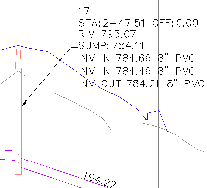
Typical structure labels from the default template have limited flexibility, such as the label shown in Figure 13-67.
Figure 13-67: An example of a standard structure label from the default template
If you highlight a structure label in profile, two cyan-colored grips appear. The lower grip appears at Profile View Elevation Zero. This is the structure dimension. Right now, it’s fixed at elevation zero, which makes sense on the basis of the default settings. The location of the structure dimension is based on the profile view, and it can be grip-edited and stretched vertically after placement.
The second cyan-colored grip is the structure-label location. It’s set to At Middle of Structure per the default settings. The structure-label location is always tied to the top, middle, or bottom of the structure and can’t be grip-edited after placement.
You learned earlier that you can grip-edit the structure dimension to override the feature settings. If you grip-edit the structure dimension, you can drag the line vertically.
If you ever need to reset or customize the placement of this label, you can select the label, right-click, and choose Label Properties.
In the Properties dialog shown in Figure 13-68, you see Dimension Anchor Option from the feature settings and a Dimension Anchor Value, which is equal to the distance you stretched the grip. If you want to shorten the line so it touches the Graph View Top, change Dimension Anchor Value to 0.
Figure 13-68: The AutoCAD Properties palette showing Dimension Anchor Option
